
A Rare Glimpse into Aerospace Forming and the Unique Method of Calibrating Forces during Forming According to the Digital Master
Hugo Groeneveld, R & D Manager at 3D-Metal Forming, captivates our readers in the following article by showing how he uses AutoForm to validate the forming of extremely thick plates into aerospace parts using High Energy Hydro Forming (HEHF), also known as explosive forming. A must-read for our community, Hugo imparts how he reduced an Airbus cockpit, normally comprising over two hundred components, down to a single plate formed part. He also shares his unique method of live calibrating the part forming process using the digital master.
At 3D-Metal Forming, we specialize in custom-made sheet metal products, particularly thick materials that must be formed into large and unconventional shapes. Some of the parts are created for the aerospace sector, while others are designed to realize a particular architectural concept. In both cases, the designs are often rather novel and exotic. We work with both sheet metal and plate metal, which area distinct terms in the English language, but they carry the same name in Dutch and German. Our unique process introduces plate forming into software intended for sheet metal forming; this has enabled us to utilize sheet metal forming simulation in new and creative applications.
In many applications we use our HEHF process only for calibrating the piece into shape. The first forming operations are done with more conventional techniques. AutoForm helps us to design these processes as well, resulting in a solution that combines the best of two forming technologies.
When we first decided to test a sheet metal forming solution within our field, we knew that it was highly experimental. Our stance was, “Okay, let’s just see what we can attain because it may at least identify a few things.” No one knew whether the software would be representative or not. So in fact, we were able to verify, on behalf of AutoForm, that their software also works for very thick plates.
Whenever we get a request for a new shape, we run some quick feasibility studies to identify any immediate risk of splits or cracks. After taking on the project, we examine the shape in greater detail with further simulations; from the results, we know what to expect for the die compensation and we can get an estimate of the actual blank dimensions. The latter is most important because we deal with blank sizes up to 10 meters wide and 120 mm thick. That is just the tip of the iceberg when it comes to applying simulation to explosive forming.
The start of the relationship with AutoForm
Of course, I was very skeptical in the beginning; but when we set our sights on qualifying for ISO9001 certification, a neighboring company insisted we have a look at AutoForm. At the very same time, we received a project led by an architect and we did not know whether a particularly unusual part was possible. The liability of project failure would fall on the customer, who did not want to take the financial risk. This triggered us to try out AutoForm. That very first project identified the critical issues for the part and showed us how to solve them by making minor adjustments. During the process, most architects don’t mind if you change the shape slightly to achieve its manufacturability as long as you maintain the integrity of their visual intention.

Fig. 1: Ventilation ducting made from a single sheet of metal used on the Smedingshuis building in Lelystad, the Netherlands
You can see from the image why the part was so difficult. It is a curved panel featuring stamped ribs from an aluminum plate 2.5 meters in length. The challenge arose from the ribs, which created very intense stretching. The question was, would it break or not? We didn’t know. Obtaining the necessary information from the software meant that we could avoid tryout loops because the part came out correctly the first time. It was a brilliant result that prompted a great sense of achievement within our team.

Fig. 2: Decorative architectural shape on the Grijze Generaal building in Eindhoven, the Netherlands.
From that first experience, we learned that AutoForm could remove many uncertainties. Since then, the software has proven a valuable tool to winning new and interesting projects; we have now been a loyal AutoForm customer for sixteen years, going strong.
Bidding on Novel Designs from Thick Plate
By default, no matter what our customers are building, it is always a novel design that is difficult to form because of the shape or the thickness of the plates. There is a real risk of buckling and having springback issues with such thick materials. It is extremely important that our customers have confidence in our expertise when embarking on such complicated projects. Simulation provides us with professional insights that enable us to submit detailed reports along with our quotes, including animations of the simulations from AutoForm and some of the plots from the Forming Limit Diagram. Armed with these tools, we can demonstrate to our clients that our approach will have a high probability of success. We normally ask for a 3D model to start with, but we will occasionally generate the 3D geometries of the part ourselves during the bidding process.
Forming plate materials means we often have to create our own material cards. In practice, during the bidding phase, we simply select a material from the software library that is as comparable as possible to the intended material. This has proven sufficiently accurate for the purpose of submitting a quote. Once we win the job, we then start tensile testing to generate a material file that will give us the highest simulation accuracy.
Thanks to the software, we can turn our bidding process around within a few days, particularly for an existing customer who is in a hurry. The feedback we receive from our customers indicates our uniqueness from other forming specialists in that respect, as we can act so quickly to develop new and highly specialized products. We really don’t have any competitors in our subcontracting field of high-energy hydroforming or explosive forming. As far as I know, there is no other specialist in the world offering this service as a subcontractor.
Integrated Structures for Aerospace Forming
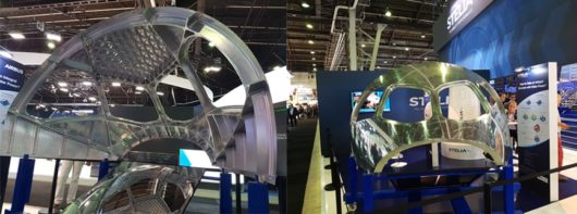
Fig. 3: Cockpit made from a single thick plate using explosive forming and CNC milling (Paris Airshow 2017)
The explosive forming work we performed on the outer panel of an airplane’s cockpit signaled real change for the aerospace industry. It was displayed for public viewing at the Paris Airshow 2017. Our work is considered revolutionary for aerospace part production because such a structure typically comprises of a hundred parts, each serving its own function. This is the case for all parts of a plane, but it is particularly applicable to the cockpit. Each and every piece carries some significance for later assemblies; you’re working with window frames, stiffener ribs, skin panes, mounting parts, among so many others. Typically, each of these units must be individually manufactured due to quality requirements. Comprehensively, this amounts to a whole lot of work to construct each part individually. And that’s before even starting on assembly. Alternatively, you could make an integrated panel by forging, which is common in the aerospace industry today. However, there are limitations to what dimensional shapes can be achieved through forging. Our process doesn’t come with those limitations – we can simply start from a raw plate, which has better properties than a casting process, and we can build the entire thing as just one part. The forces in the HEHF process can be much higher than any press in the world could ever deliver. This was a major breakthrough for our industry.
Typically, there are some parts of a cockpit that are only brought into tolerance once everything is assembled. The entire assembly is pulled together by its ribs. For us, this means the main challenge we face is springback. We cannot pull everything together as there is no assembly. We need to deal with springback after removing the part from its closed die, or after the explosion itself. Following, we apply machining to create the important ribs, which would otherwise have to be assembled into the structure. The residual stresses left in the material are also released once you begin milling out the inside of the plate for the cockpit, but the machining process is highly accurate. We predict the springback of our forming using AutoForm, followed by another prediction to determine the springback after milling using Ansys.
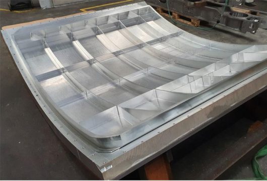
Fig. 4: Airplane cargo door example made from a single plate of aluminum.
Many companies in the aerospace industry utilize Ansys and Abaqus for a variety of functions unrelated to sheet metal. Thus, bringing software that is specialized in forming automotive sheet metal parts into the aerospace industry demonstrates its value within the process chain. We have discovered that the combination of AutoForm and Ansys forms the perfect complement for our workflow. What AutoForm brings is an especially dedicated system for sheet metal forming which is a much faster and simpler avenue to obtaining meaningful results. AutoForm is used to simulate the deformation of the plates and Ansys for the machining. For all large parts, AutoForm is mainly used for determining the springback correction of the die, equipped with perfect tools for just that purpose. A major reason we consistently use AutoForm is the speed of calculation. In just half an hour, your simulation is ready. In many simulation packages we have tried, particularly in the aerospace industry, you have to input so many variables that mistakes are easily made; this is especially true for the meshing. But thankfully, AutoForm performs all of that nearly automatically. For sensitivity studies, I can use AutoForm’s standard Sigma settings to easily investigate the process robustness.
From Single Part Production to Assemblies
Today we are continuing to expand our services thanks to simulation. We do explosive forming for a customer in the medical sector, who has now subcontracted us to perform 3D laser cutting and assembly of parts received from our suppliers. We don’t normally offer assembly, but the customer’s request has given us the good fortune of becoming part of the pilot project for AutoForm-Assembly; and in doing so, we have the opportunity to expand our services. Chovav Mordechai, our contact at AutoForm, bolstered our skills so that we could use this module to solve several of our customer’s existing problems. Now we’re using the module for another customer. Initially, we were contracted to make single parts with the assembly performed by the customer. However, after they assembled our parts together with those from other suppliers, there were some deviations from the intended part shape. Now we handle both part forming and assembly. Thus, the module allows us to offer certain business add-ons, which would have otherwise gone to another subcontractor.
We have been shaping parts and products using high-energy hydroforming for 23 years. But we are seeing our business increasingly combine this technology with other professional forming technologies, such as the combination of explosive-forming and press-forming. As a result, simulation is continuing to gain importance. We now have obtained unique expertise in designing and manufacturing our own press forming systems. These systems include live feedback that show how the real process correlates with the AutoForm simulations.
Live Calibration of Forces and Material Flow Using a Digital Master
What we have achieved through forming simulation in the realm of forces calibration in conventional press forming is entirely novel.
Our control system (programmed in LabVIEW) gives live feedback of the force buildup during a press stroke as well as the draw-in of the blank at several places.
Our forming is completed using hydraulic cylinders with a ram which allows us to adjust the process parameters during the stroke.
In the automotive world, where the material might be worth a few Euro’s, it is possible to do lengthy tryouts in the press to match reality to the simulation.
In the aerospace world, with its demand for huge shapes and thick plates, it is not cost effective to perform lengthy tryouts as it is common for a part material to cost over 10,000 Euro’s. Being able to adjust the process mid-stroke is key here.
We start by running simulations to understand which process conditions we need in order to get a good (“green”) part.
Next, we perform a sensitivity analysis using AutoForm Sigma to understand which forming conditions would produce undesirable results. This way, when we compare our control system output to the AutoForm simulations, we could immediately determine what caused the problem and what counter measures need to be applied.
In practice, we use two outputs from AutoForm. One is the draw-in graph which we use to verify the material flow of the blank at certain points. If a certain binder pressure is not high enough, the material flow will be too high compared to the simulation, which we know from the analysis will cause some buckling later on in the process. The counter measure in this situation would be to increase the binder pressure.
The second output is a graph of the press forces vs. the stroke. During the physical pressing of the part, we are able to track the forming forces in real time. When compared to the graph in the AutoForm digital master we are able to observe, for example, “Okay, here the forces are increasing rapidly, but that increase doesn’t appear in AutoForm.” Therefore, we know we have to intervene because something undesirable is happening. The counter measure in this situation is less intuitive – the sensitivity analysis indicated we needed to improve the lubrication conditions of the punch.
Digital Fixturing
Another benefit which AutoForm Assembly offers is that the fixturing of prototypes can be performed digitally. Our large parts can be very flexible and it can be complicated to fix a part correctly on a measurement jig. Normally we position a part, measure the shape, analyze it, and modify the fixturing accordingly. This can be very time consuming. However, we can now simply support the part in three points; measure it and then do the fixturing in the digital.
Carrying out fixturing in AutoForm Assembly is also very helpful when we want to determine the shape change due to the aging process. The shape change is in the order of only 0.1% for precipitation hardening of aluminum alloys, but that is significant for our parts which are a few meters in size. In AutoForm Assembly we can easily fixture the measurements of a shape before and after aging in such a way that one shape is the scaled version of the other. It would be very complicated to do this with a physical measurement jig because the shape change from aging is different in the rolling direction relative to the transverse direction. You do not know in advance what shape a measurement jig must have in order to get a result that can be scaled to fit on the other measurement jig.
In conclusion, because of the specialized parts we have successfully produced, we have won some incredible aerospace contracts. We have supplied parts for OEMs that want single part integrated structures instead of multiple part assemblies in their plane models. Without AutoForm, we would never have won such prized contracts. The aerospace sector has been searching for a long time for a solution to quickly and easily assess the feasibility of new forming processes. Given the scale of the investments in tooling and part material required for proving them feasible, it is not commercially possible to experiment with such unconventional ideas. It is only through digital analysis that we could identify the feasibility of those ideas and the adjustments required to bring them to life.
Keywords: Aeronautics, Aerospace


?")


