
In our previous articles, we covered how aerospace part supplier Senior Aerospace Thermal Engineering (SATE) a UK-based aerospace component manufacturer and part of Senior plc, an international manufacturer of high technology components and systems, integrated forming simulation into their New Product Introduction (NPI) business. We also looked at a case study of how they used simulation to validate a previously un-tapped forming method and then implement it into their manufacturing process. In this article, we explore another specific case encountered by SATE. This is part three of a three-part series.
SATE’s engineering team is predominantly comprised of manufacturing and NPI engineers who are adept in process engineering and project management, as well as highly skilled tooling engineers with extensive experience in press tool design.
While SATE has a greater focus on the manufacturing of products as opposed to design, it leverage its technical expertise to suggest changes at the appropriate stage of product development to improve the formability of a particular part. While this was previously performed based solely on engineering knowledge, the introduction of AutoForm’s simulation software has revolutionised the process. In this article, we explore an example where SATE were able to do just that:
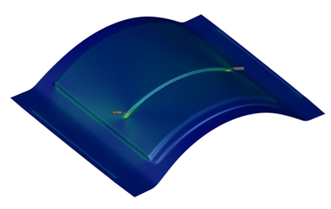
Fig. 1: Pressing operation simulated using the CAD model originally supplied by the customer (~30% thinning)
The customer reached out to SATE with an issue: they were unable to reach the depth requirements of a newly designed part using their in-house hydroforming capabilities.
As this part was still at the pre-production stage, only a CAD model and basic tolerance values were provided as part of the RFQ. Upon initial review of the supplied data, SATE engineers observed a deep curve with a stiffening feature running most of the width of the part.
The SATE team, in collaboration with AutoForm engineers, evaluated both cold and hot forming methods. Given cost and time constraints on material characterisation, they opted to use a stock material card from the AutoForm material library.
The costs associated with material characterisation at high temperature, estimated at upwards of £10,000, would have made this analysis at the feasibility stage impractical. Instead, the team leveraged a workaround to assess the part using the closest material model. While they recognised that this material wouldn’t precisely match the characteristics defined in the component definition, its mechanical properties were very similar. Notably, the AutoForm material was expected to thin faster due to reduced elongation. The rationale was to achieve an acceptable level of thinning in the simulation, anticipating improved results during physical part forming. Even so, the best result achieved with the initial design exceeded 28% thinning.
Moreover, the isothermal process would ensure a spring-back-free part, so they could discount this from the simulation, simplifying the simulation stage to focus solely on formability and thinning.
The customer had initially intimated that they would be open to design modifications to facilitate better formability. The initial simulation results led to hot forming emerging as the lowest risk process considering formability, thinning, and spring-back. However, the team determined that the stiffening feature would require modification if they were going to be able to form the part in a single stage. This hot forming proposal was presented to the customer, who provided provisional approval, allowing SATE to revisit the design within the AutoForm environment. The engineers started by eliminating the problematic feature altogether, and simulation iterating a replacement aimed at improving formability while adhering to mandated dimensions.
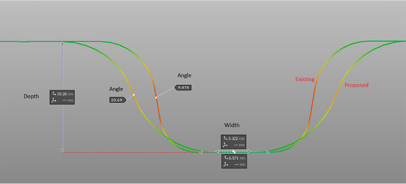
Fig. 2: Cross-sectional view comparing existing and proposed geometry
After analysing various design iterations, the SATE team opted to remove the almost vertical side wall that connected two radii in the existing design. Instead, they proposed a broader angle of approximately 20° for the radii meeting point, instead of the initial 9° angle, whilst maintaining the 10mm feature depth requirement. The entrance angle at either end of the feature was also relaxed, creating a new feature that gave the team confidence it would meet the specification.
Once satisfied with the design modifications, the team sent the design to the customer who, after a short period of review, agreed to implement the suggested changes and awarded the order to SATE.
While the design revisions addressed critical concerns, the tool surface would still require some refinement prior to being commissioned for manufacture. Specifically, an out-board bead feature was added to the tool design to relieve compression on the joggled-flange. This was achieved by stretching material into the channel created between the flange and the new feature, eliminating any wrinkling or creases. This issue had been anticipated during simulation, highlighting the invaluable role of simulation in pre-emptively identifying and resolving problem areas. Without simulation, this issue would have only become apparent after the tool was produced, resulting in costly corrections, particularly given the limited order quantity of the part.

Fig. 3: Bead feature added outside of the final part geometry to ensure sufficient material stretch on the flange
The final area of focus was to reduce the level thinning observed between the stiffening and flange features, caused by both features competing for material at the same rate, a figure that initially stood at 24% of the nominal sheet thickness. To address this challenge, cut-outs were strategically added to the blank in close proximity to the stiffener. Creating this divide allowed material to flow into the stiffener and significantly reduce the maximum thinning to 4.5%.
Simulation was crucial in helping to predict the level of draw-in on the adjacent material, and then to determine the size and position of the cutouts, ensuring that they would not encroach on the final part profile.
These initiatives resulted in a right first-time result following tool try-outs. Notably, the first part was gifted to the customer free of charge.
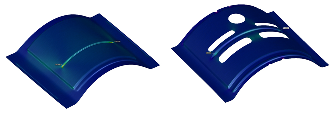
Fig. 4: (left) Original. (Right) Modified part.
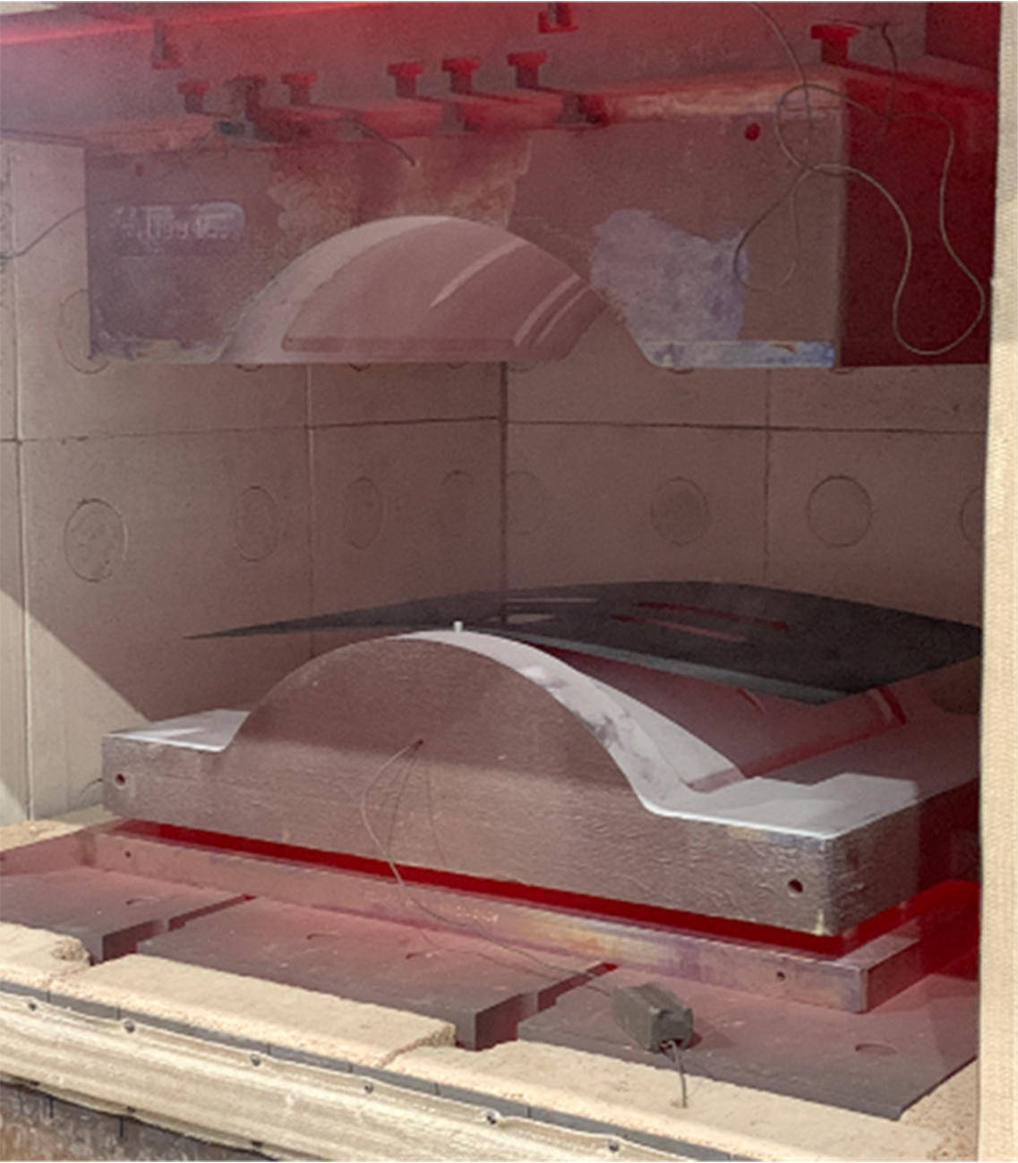
Fig. 5
It took SATE four months to progress from tool design to First Article Inspection and fixed process approval – a remarkably short timeline, made possible by simulation. The same part would have taken a minimum of eight months without simulation. Plus the entire part, including all post processing, was produced in-house at SATE, showing how their innovative approach saved both time and cost.
Summary
In closing, the implementation of software simulation technology has delivered several benefits to SATE, including:
- Quick and accurate price quotations.
- The ability to easily study various alternative forming methods, assess their advantages and disadvantages, and determine the best and most cost-effective approach.
- Effective communication with customers regarding manufacturing feasibility issues, accompanied by proposed solutions through geometric modifications.
- Achieving a fully conforming part from the first forming cycle, for the first time.


?")


 Process: Hot Forming Challenges Part 2")