
Series index. Part 1, Part 2, Part 3, Part 4, Part 5, Part 6
What’s so super about superplastic forming?
Superplasticity is the ability of certain materials to exhibit extensive plastic deformation at an elevated temperature prior to failure without necking. A large number of materials exhibit superplastic behavior but only select few, such as aluminum, titanium, nickel, and ferrous alloys, have found commercial applications. These heavily rolled materials with fine grain size (typically less than 10-20 μm) are deformed within a controlled strain rate (usually 10−5 to 10−1 sec−1) at temperatures greater than 50% of the material’s melting point to produce a tenfold increase in elongation (200% or higher) compared to the conventional cold forming process. Titanium alloys such as Ti 6Al 4V and some stainless steels are heated to around 900 °C, whereas aluminum alloys (e.g., AA5083) are heated to between 450–520 °C to promote superplasticity. During superplastic deformation, a gas pressure in the range of 0.1 to 2.1 MPa is applied to the superplastic sheet, causing the material to stretch and thin uniformly across the entire part. As a result, the metal does not experience necking or local thinning, which often leads to tensile fracture. Inert gases such as argon or nitrogen are used in the superplastic forming (SPF) process because they do not react chemically with the sheet metal.
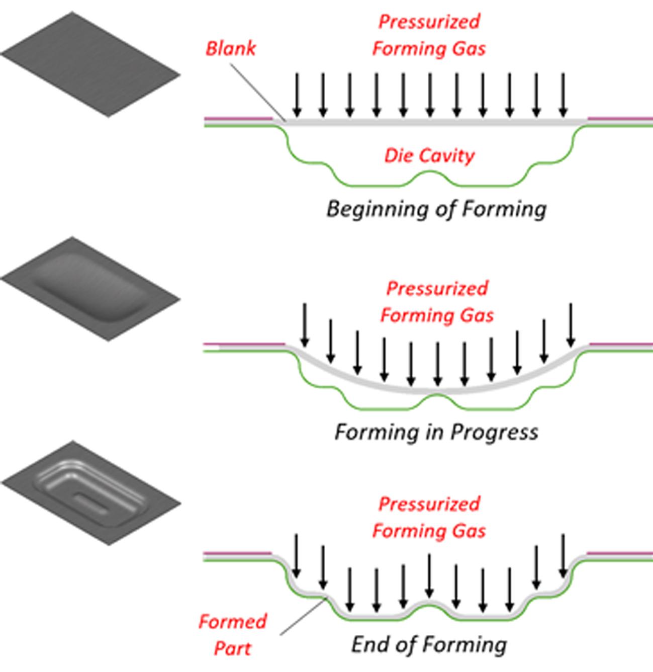
Fig 1. Schematic of Superplastic Forming Process
SPF is ideally an isothermal process, meaning the tools, blank, and forming gases are all kept at a uniform temperature. The heated blank is loaded onto the tools, which are kept at an elevated temperature, and the forming takes place when the pressurized hot gas is blown inside the cavity, molding the blank into the formed part without springback or residual stress. The aerospace industry has used superplastic forming of aluminum and titanium to form specialty products for more than 25 years. Moreover, this technology has also proved to be efficient in the manufacturing of railway and bus components. However, because of the slow cycle times (in the range of 30 minutes per part produced), SPF has remained a niche process, especially for the automotive industry which is accustomed to faster forming processes that produce parts in seconds. Nevertheless, carmakers are still interested in SPF technology because of its economic advantage when producing small to medium complex panels that would otherwise require expensive tooling and materials (low formability) with conventional forming processes.
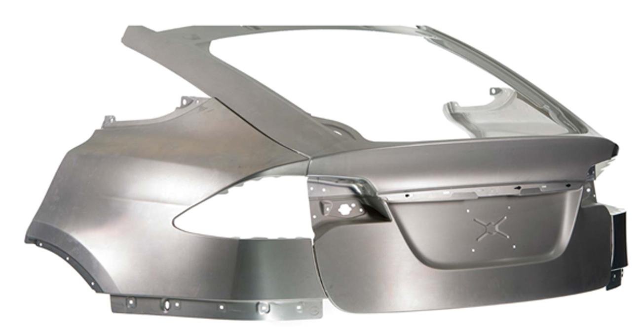
Fig 2. Automotive Aluminum SPF Panels (courtesy of Verbom)
How to model the SPF process
The main principle of the SPF process is rather simple. However, modelling requires accurate consideration of its essential elements. Heat transfer between the sheet, tools, and forming medium should be accounted for. The complex material behavior should also be modelled by considering temperature and strain rate dependent hardening. If necessary, the temperature dependent r-values can also be included in the material definition.
There are generally two use cases when modeling the process conditions:
- Pressure profile is not known beforehand: Here, the aim is to optimize the pressure-time profile to achieve an optimized process time. A major characteristic of all SPF processes is speed, which must be controlled to keep the strain rates in the superplasticity range. Process engineers can set a target strain rate and a maximum thinning amount. Then they will begin with a “guess” pressure-time profile and optimize it by maintaining the process around the set target strain rate. This is achieved through automated simulations.
- Pressure profile is already known: In this case, process engineers can directly define the pressure-time profile, with which the simulation is performed.
For demonstration purposes, we’ll look at the simulation results of an aerospace lipskin part made of 2.0 mm thick AA5083 material. Figure 3 shows a section view of a formed lipskin at the end of the SPF process where the sheet is clamped between the top green tool and the bottom magenta cavity with the gas pressure applied from the top. The sheet, tools, and gas are all set at a constant temperature of 500°C during the forming process.
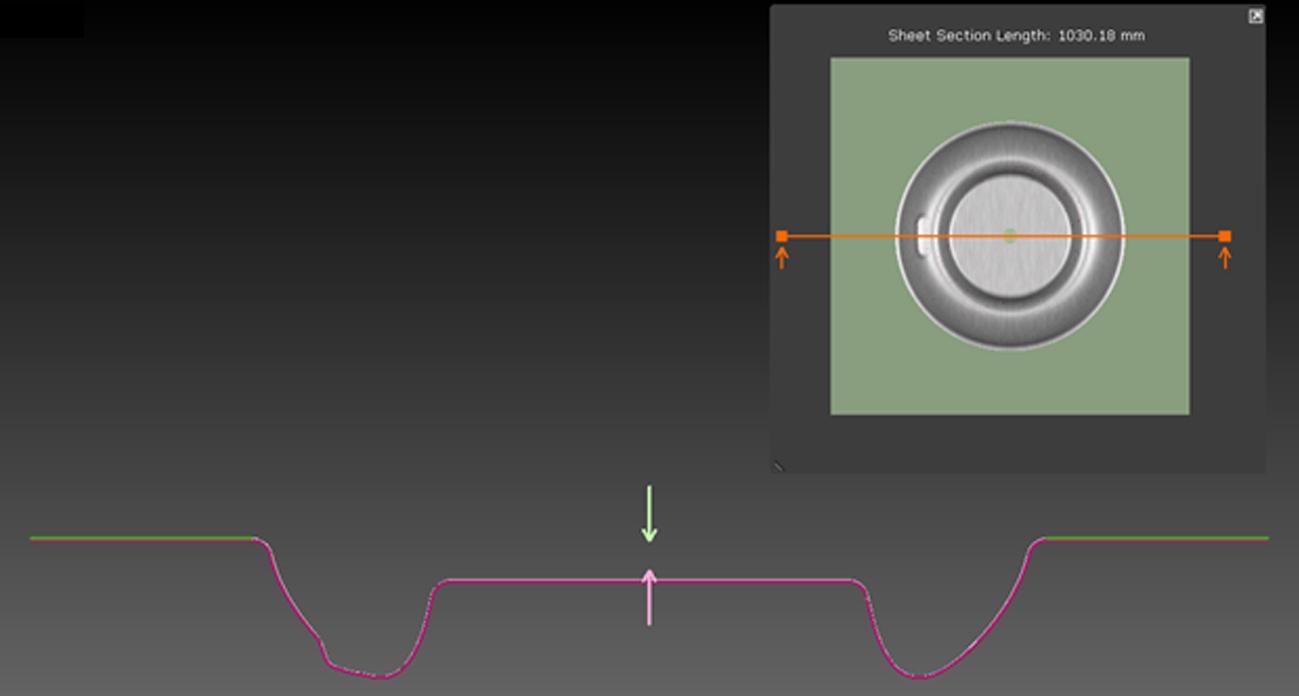
Fig 3. Cross-section view of a superplastically formed aerospace lipskin
The software’s Rate Control option will adjust the gas pressure based on the target strain rate and maximum allowable thinning, which in our case are set to 0.009 sec−1 and 60%, respectively. With this setup, the simulation outcome shows a maximum thinning of 58.2% on the formed panel (shown in Fig 4.a), while the contact distance values are less than 0.058 mm (shown in Fig 5.a). Contact distance is the gap between the formed panel and the tools; lower contact distance is an indication that the applied gas pressure is sufficient to fill the cavity. The resulting optimized process takes 105 seconds to complete.
A second simulation was carried out using the Active Pressure option, where the pressure was raised linearly from 0.0 MPa to 2.1 MPa over 300 seconds. The simulation results produced a panel with maximum thinning of 67.3% (shown in Fig 4.b), and contact distance values of less than 0.069 mm (shown in Fig. 5.b). The resulting part qualities are very similar in both simulations. However, the second simulation yields an optimized process that requires 1/3 of the time. The process engineer can now export the resulting pressure-time curve for the machine setup in the real process.
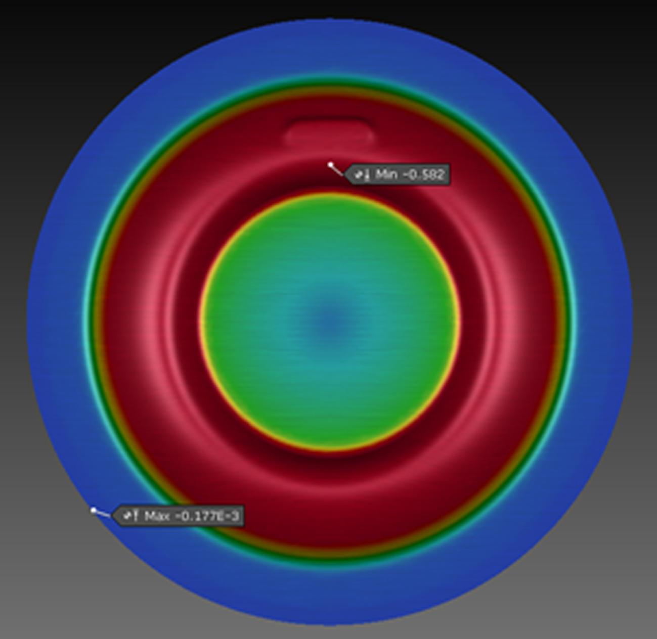
Fig 4.a. Thinning Plot with Rate Control
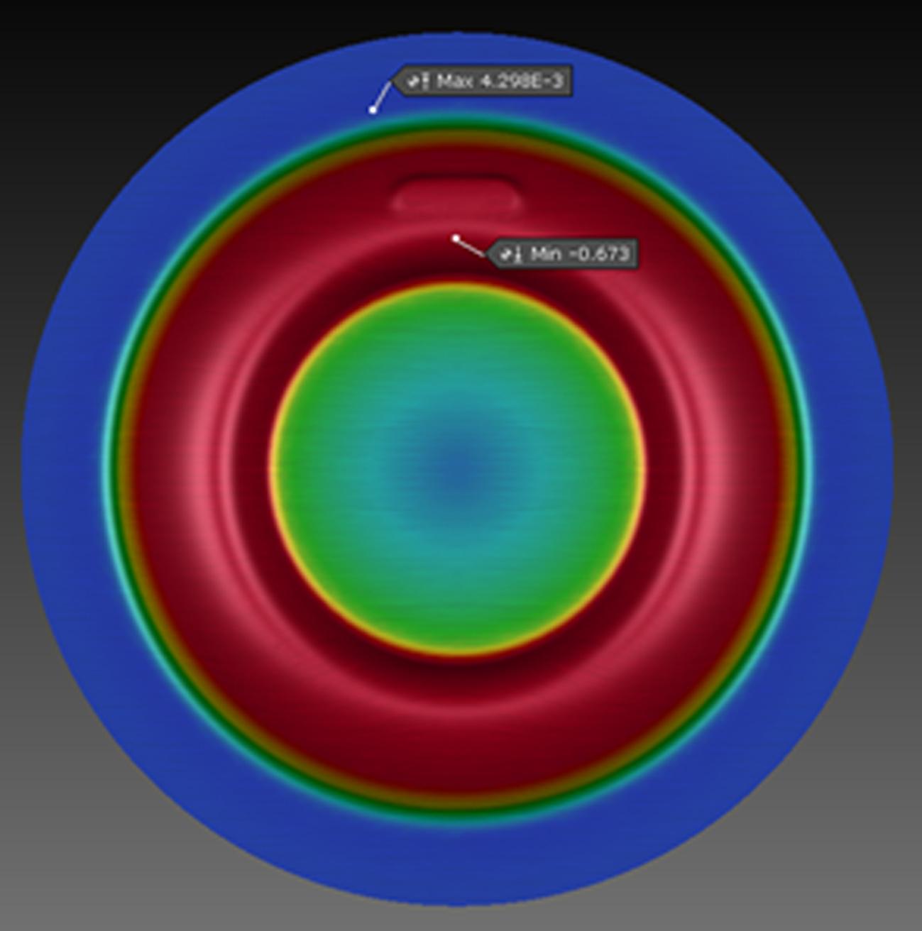
Fig 4.b. Thinning Plot with Active Pressure
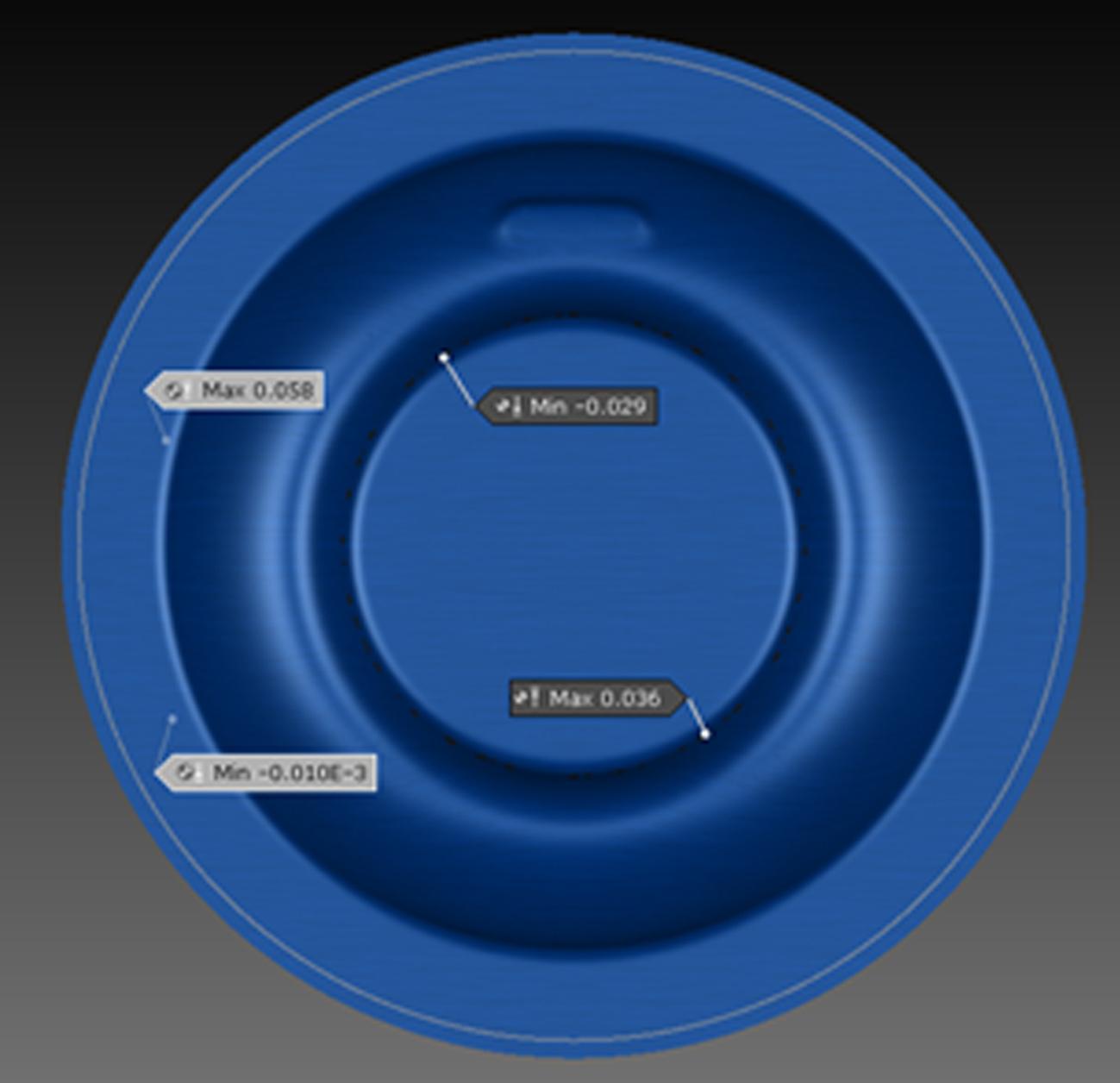
Fig 5.a. Contact Distance Plot with Rate Control
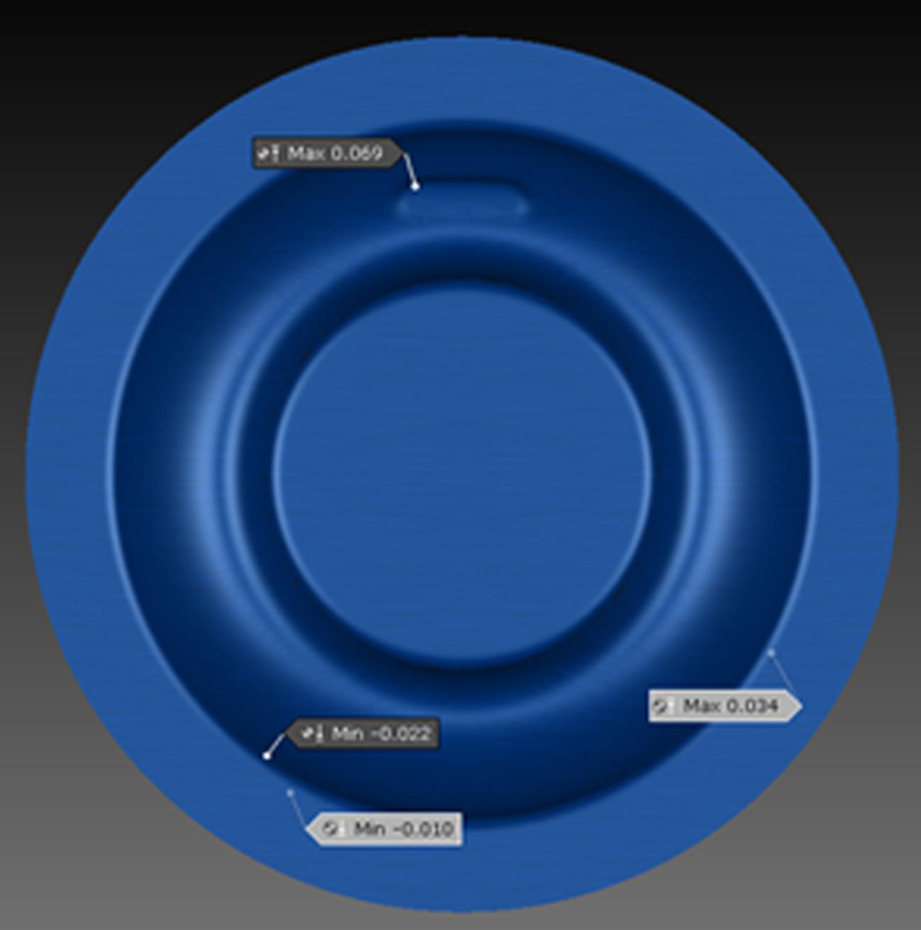
Fig 5.b. Contact Distance Plot with Active Pressure
Using AutoForm’s software, it is now extremely convenient to simulate a superplastic forming process. Armed with the correct material card and the processing conditions, the user can quickly evaluate the simulation outcomes. The simulation can also be easily optimized by changing the process parameters such as pressure, strain rate, material thickness, and tool geometries, to name a few.
In part one of this series, we covered Process Engineering with New Materials: Hot Stamping Challenges. In part three we cover Heated Tools: Solving the Challenge of Tool Surface Temperature Distribution.


?")


