
It is easy to believe that if we have two or more parts in tolerance and we assemble these parts, the final assembly must be in tolerance too. However, it is not always like that due to reasons like residual stresses and stiffness that, when added to a small deviations from each part, can lead to an assembly being out of the tolerance.
When this happens someone has to resolve it, and there are different ways to do so. Usually, this decision depends on the parts involved on the assembly. When talking about automobile parts there is often an outer part (Class A), and those involved in that compensation approach must be very cautious.
The first approach is part compensation. In AutoForm Assembly, users can choose any part (or parts) of the assembly to compensate. In doing so, the part shape morphs to a new, non-nominal geometry in order to drive the complete assembly to be within tolerance. Generally, the part selected for that compensation is the most rigid part of the assembly so that this part can move the rest of the parts to the desired tolerance position. Users can easily perform stiffness analysis in AutoForm Assembly too, allowing them to determine the most influential parts in the assembly.
A second approach is adjustment of clamp position or join sequence. This method in Body-In-White is known as shimming and teaching. Shimming is the compensation of the clamping points and Teaching is the compensation of the welding points. Usually these two modifications go hand in hand.
Some departments like Chassis, Structural Parts or Body-In-White Planning compensate assemblies in this way. As they do not have physical parts at this time, they usually modify the clamping points when welding in order to join the parts in a compensated position. Then, after releasing the clamping system, the assembled parts go to the tolerance position.
In simulation, the first iteration is completed with each clamp and weld point definition over the nominal surface, which is imported when setting up the assembly process in AutoForm. Looking at a section for a weld location, we can see something this:
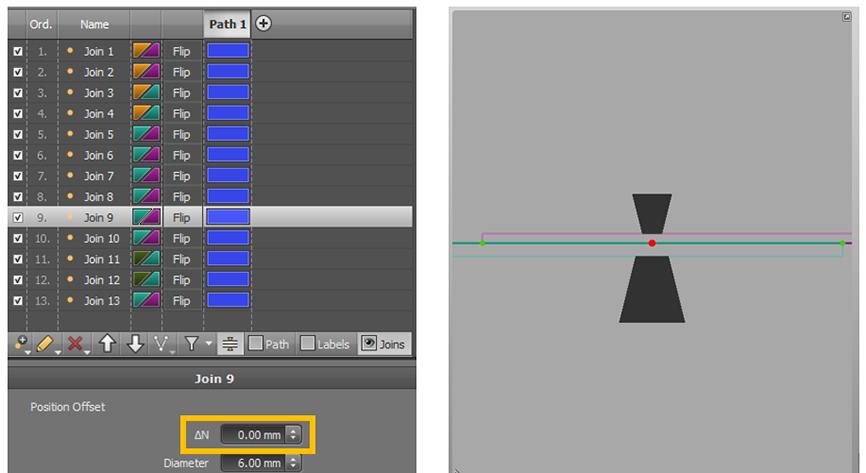
Pic.1: Left: Welding point list definition; Right: Section across a welding point
We then must run the initial simulation with all the processes defined in this way, and analyse results to see if there are surfaces out of the desired position.
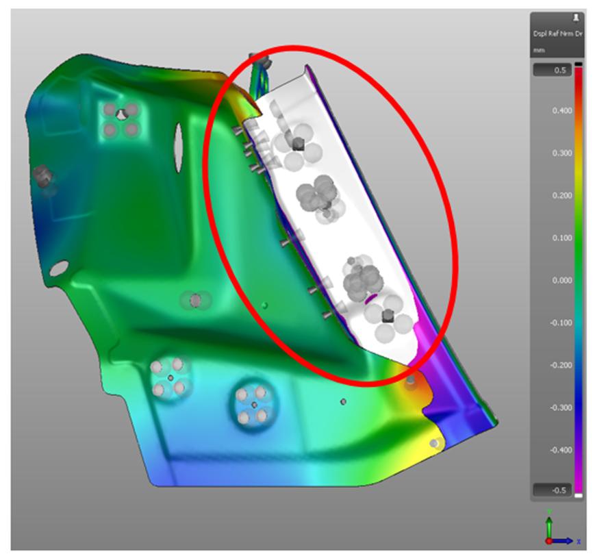
Pic.2: There is an area out of tolerance (highlighted in white)
If we find an area out of the tolerance, we can try modifying the clamps’ and welding points’ positions normal to the surface. For that purpose, in AutoForm Assembly we have a specific box, the “ΔN”. This functionality allows a direct modification of a distance at the point position normal to the surface.
This “trial and error” process in the physical world, which also carries inherent costs, can now be performed virtually in our software. Using this more efficient approach allows significant cost and, maybe even more importantly, time reduction.
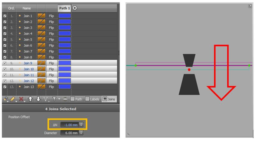
Pic.3: Left: Welding point list definition, ΔN applied over the four Joins affected on that area; Right: Section of a compensated Join
After completing some trials and simulating the final version we can find that now we are inside tolerances, giving us a starting point for our physical equipment at tryout.
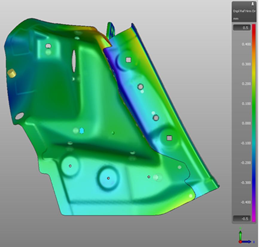
Pic.4: Good results after Shimming
After doing all these modifications from nominal definitions, users from these departments are usually worried about the reaction forces on the joining points or clamping system. It is to be expected, as they have just modified something that was previously defined as nominal. Furthermore, the reality is that when they compensate these points they actually are increasing the reaction forces on the joining points and on the clamping system. Without simulation software, it is not possible to know all these reaction forces, so simulating these modifications virtually can validate this compensation process.
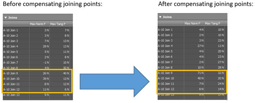
Pic.5: Reaction force before and after Shimming
Having seen an overview of that process, we can say that those responsible for solving assembly problems would start modifying clamps and joins in the affected areas (highlighted in red circle in Pic.2). They try different values and combinations, and after some trials can achieve a good deviation allowing the assembly to fall within the desired tolerance. Sometimes this can be achieved within in a few adjustments, but often this can take multiple shifts and additional time in the physical world. In some cases, results are only marginal after spending considerable time. Having AutoForm Assembly to find these virtual solutions means time and money can be saved.
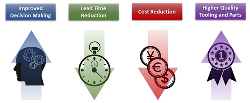
Pic.6: Benefits of using AutoForm Assembly
- Assembly Solution will lead to improved decision making by earlier identification of problem parts or processes.
- Lead Time Reduction by creation of a robust design process and shortened trial time.
- Cost Reduction through fewer tool modifications and improved production efficiency.
- Higher Quality Tooling and Parts that are more accurate and robust.
This is a common approach from many users in Body-In-White departments. In the last months, our office has completed many demonstrations of this approach, and the feedback has been very positive. Usually they don’t have any software to do this analysis, and AutoForm’s user-friendly interface makes this beneficial to a wide range of departments. Now these users can virtually predict what happens with shimming and teaching, giving them a great starting point when assembly trials begin!
To learn more about what AutoForm Assembly can do for you, contact your local AutoForm office for more information..


?")


