
Seamless dataflow brings optimally compensated surface quality and dimension into the steel
Delivering panels with high dimension and surface quality within ever shorter lead times puts toolmakers under pressure. Toolmaker Kanagata has explored a new approach based on seamless dataflow between CAE and CAD to cut their tool tryout from 7 loops to just 1 in a recent door inner project. This article reveals the approach and shares Kanagata’s learnings.
Today, there is a data disconnect between the stamping process concept in CAE and the final stamping tool milling data in CAD. First, process engineers test and optimize the stamping process in CAE software like AutoForm before moving to the next task of creating the final tool surfaces in CAD for milling. Then, most companies start over by manually recreating the tool surfaces in CAD. This manual process leads to discrepancies between the validated process concept and the milled data. As a result, we cannot achieve the optimum surface design in terms of surface and dimensional quality. Furthermore, this manual rework leads to higher workloads and manual errors. For instance, problems that have already been solved in the process concept stage may still reappear in the milled tool due to the manual nature of this workflow.
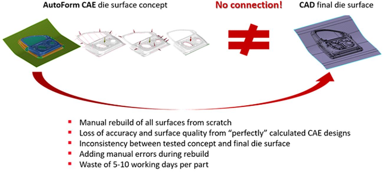
Figure 1: The disconnect between process concept and final process design leads to waste and manual errors
With this challenge in mind, Kanagata and AutoForm have started a pilot project for a door inner, leveraging AutoForm’s compensation technology and a seamless dataflow between CAE concept and the CAD milling stage. Christoph Weber points out, “We believe that only a seamless dataflow from engineering to milling preparation ensures that we bring the digitally validated process – optimized for excellent surface and dimensional quality – right into the tool steel on the shop floor.”
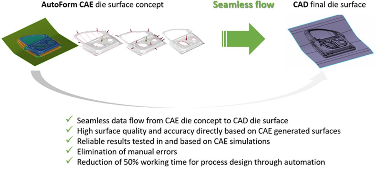
Figure 2: Seamless dataflow cuts manual rework and brings all digital process knowledge directly into the steel
The project team approached this door inner case in three steps. First, the team identified and compensated dimensional springback and surface defects in the process concept stage. Then they handed over the data via a specific AutoForm file format to be used in CAD to construct a nearly matching final tool surface. Second, they rebuilt the tool surface directly in CAD based on the concept data to ensure optimum alignment. Third, they milled the tool exactly according to what had been validated in simulation and executed the tryout according to the digital process blueprint. As a result, the project team saved 50% engineering time in CAD re-building and delivered quality panels right from the first tool tryout.
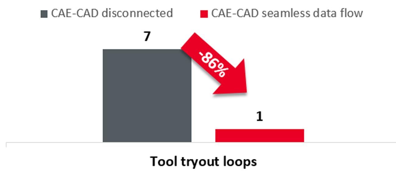
Chen Xinzhang, Vice GM of Shunde Kanagata, revealed, “We used Process DesignerforCATIA to rebuild the surface and create milling data in a door inner project. This methodology can help us to improve work efficiency by 50% compared with our traditional approach. Furthermore, this approach reduced our tool tryout loops from 7 to 1, delivering 85% qualified parts in the first loop.”
(Images used in this blog are not specific to this customer and are intended for an explanation of the idea only.)


?")


