Steve Hackett Shares the Success of his Eight Person Forming Consultancy
Curve Engineering is an eight-man operation in England specializing in process simulations, blank size minimization services, die design and commissioning for Tier 1 suppliers and OEMs. In the following interview, the company’s founder and director, Steve Hackett, reveals how it has succeeded in becoming a Tier 1 supplier’s first call for handling blank size estimations. When a quote pack arrives from an OEM, it generally comprises a very large number of parts. Thanks to Curve’s quick turnaround time by employing digital engineering software, its Tier 1 customers can, in turn, quickly respond to OEM invitations for project bidding. In a recent project, for example, Curve completed blank size estimations for a total of 327 parts, which is astounding considering the pace of bidding. Let’s find out just how Curve achieved this.

Curve Engineering uses simulation for two of its main services: early feasibility and optimizing existing stamping operations. As a digital engineering consultancy, Curve does not handle any of the manufacturing, although it is still involved in many of the stages.
Steve Hackett explained the role of simulation in these two services:
“When identifying an accurate blank size, we run an initial early feasibility check. We confirm if a part is feasible, or whether it could be with a little more time spent on its design. Otherwise, we reject their part as fundamentality unfeasible, informing that it needs to be divided into separate parts that can be individually stamped and then assembled. When we started getting contracts for a huge volume of parts, AutoForm-StampingAdviser became our workhorse. This is especially true in the case of arriving at an accurate strip concept for progressive die tools. The software is invaluable, as otherwise, we’d spend a considerable amount of time laying strips out. Trying to unfold all of those parts, making an educated guess at blank development, and then manually laying it into a strip is just too demanding.
“Previously, we estimated blank sizes based on our experience. We have a core team of experts who know stamping. In reality, assigning them the laborious task of tediously unwrapping parts would be a waste of their true professional value. Using AutoForm-StampingAdviser, you come to the same result without having to do it all manually – it will unfold the blank, generate a quick screen report of a strip concept and there it is, the blank is flattened out in just ten minutes. In comparison, unwrapping it manually in CAD would take two hours. We could hire less skilled engineers to carry out that task, but the software does it all for us. Our goal is to fight for the smallest possible blank. Moreover, achieving this with less manpower is obviously a win, not only for our organization but also for our Tier 1’s, who are also more likely to win the contract once they bid. The blank size estimations we supply have proven to be accurate.
“We have become the first choice for our customers because we guarantee a quick turnaround. Our Tier 1’s wish to quickly place their bids and commence stamping in their press shop. In their position working with high-volume OEMs, just 2mm less to the pitch makes all the difference between winning and losing the job. We know our service is high quality because our Tier 1’s keep bringing their business to us and they keep winning the work. Then there is the question of accuracy. In practice, we can observe how close our initial estimation was because the parts they win are again given to us for in-depth study. That process is interesting because in the first phase, the Tier 1 will target the parts suited to their own press lines and those correspond to the parts that we originally received for blank size estimations, prior to their bid. Naturally, an OEM won’t give all their parts to one supplier. Our Tier 1 will win approximately fifty or so parts out the entire series. So, we first estimated their blank sizes and now those parts return to us to undergo comprehensive analysis, which may lead us to submit a change request on part design.
“During this process, we communicate with the toolmaker, who keeps us in close contact with the OEM, leading up to the project handover. The toolmaker may wish to impart some additional changes, but we are assured that upon handover, we have given them a feasible process and a feasible part right from the get-go. Historically, this has not always been the conventional process. Normally, the toolmaker performs all the feasibility; but this can kill our Tier 1 customers, because a lot of time is burned trying to reach feasible part design when really, they should crack on with die design. Therefore, that is where we fit in as a service, much earlier than the majority of Tier 1 service providers. As a business, it is better for us to operate at this stage of the process because we have more opportunity to make feasibility change requests, since there is more fluidity when development is not yet tied up with packaging and design. It’s important to note that as soon as the part is handed over to the toolmaker, the OEM will have one toolmaker creating this part, and another toolmaker building its mating part at an entirely different company. At that point, if toolmaker A wishes to make changes that impact toolmaker B’s part, then the second toolmaker is going to promptly charge the OEM for the requested engineering changes. We are party to all of the parts on a particular assembly, so we benefit from the entire overview; a toolmaker is often only party to certain parts within that assembly. So, here’s the beauty of our service: if we want to change one part that impacts another part, we can raise a request for both, and it doesn’t cost anybody any extra money. Aside from improved transparency, the cost typically experienced when toolmakers put in a change request is reduced solely to our cost for simulation.
“The second part of our services is based purely in optimizing existing stamping operations and enabling customers to reduce the amount of scrap. This brings the challenge of adaptability, as there is no room for specialization within a certain range of parts or operations our customers deal with. In one project, we will be employed to handle bent progressive tool brackets; another, body sides; and another, hemming simulations. There are various ways we achieve blank size optimization on running jobs and we have our own trade secrets, which we won’t publicly share as they give us a competitive edge. For a running job, we scan the dies, analyze the current blank, and use AutoForm-Sigma to reduce blank size as small as we possibly can. Using the software, we can do robustness comparisons between different blank sizes. If you get the same results for the smaller blank as the bigger blank, then you’re good to go.

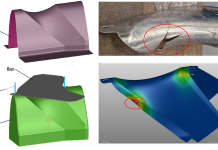
Fig. 1: Example battery tray illustrating geometric challenges for forming.
“During that process, however, you’ve got to be mindful that you’re not simply making a pressed part and a green drawn shell and then you’re done. You have to be mindful that these dies run at twenty plus strokes per minute down a transfer line and that it’s all about run rates. When we look at parts, it’s not just in terms of forming feasibility. We also have our eye on ensuring that they can reach a good run rate with the smallest possible blank. This is where the part supplier will either make or lose their money in the end.
“We are currently doing a fix job on a production run that is seeing a high scrap rate. We’ve scanned the die, run the simulations, and offered our recommendations for changes they need to make in order to reduce their scrap rate. Believe it or not, often it comes down to blank location. In jobs like this, we might ask customers to adjust their blank position, die geometry, bead position, blank size, etc. – whatever factors need to be adjusted. There are limitations, as you can’t change things like the blank holder shape, since the die has already been manufactured. These jobs require a speedy response time because you need to find a solution that can be achieved quickly to avoid running down a huge amount of blank stock. That’s why we see Tier 1’s consistently maintain relationships with their go-to experts. In the case of the problematic part experiencing a high scrap rate, we found that the original simulation (provided by another simulation company) was not set up quite right, usually as a result of being too hasty.”
This leads to the question of accuracy, to which Steve Hackett replied, “Nine times out of ten, I find that these problems arise because someone has done something wrong during the setup of the forming simulation, or they just haven’t taken their simulation far enough. They reach a point where they say, ‘Let’s machine the dies now because we’ve got to meet this deadline.’
“The other thing we sometimes use AutoForm-StampingAdviser for is parts with difficult shapes; for example, our current project on battery trays has some sticking points. The problem with these parts is that they are completely flat, with a large hump geometry at the other end, for the electrical cables and couplings outlet. As a result, you end up with a huge flat area, and then deep draws at one end. Springback issues make these parts tricky to make because you can’t compensate a flat shape and the majority of the part is indeed flat in-plane. Now, you could add some geometric features such as ribs to stiffen the part; but the problem is, due to the large body-side size and because of its deep draw, you need to draw and then re-draw during part forming. However, because there are many features within the part itself, a second press is used in your press-line that has less tonnage than your first press. As a result, you start running out of tonnage for all the definition required in the deeper section of the part. The shape is very specific, as it has to be sealed for fire safety reasons. Because you can’t have a burr on one side of the part, you also have to draw them invertedly – actually upside down, like a toggle draw. Once you get past the draw, it’s easy because the rest of the part is flat.

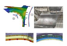
Fig. 2: Feasibility analysis and process improvement.
“Jobs like this take a long time to run in simulation, even though we’re running on eight cores. The battery tray project, for example, takes four to six hours to run because of all the details and small elements due to mesh refinement. After the initial simulation, we know some changes need to be made and we’ll run it through Formcheck, which is part of AutoForm-StampingAdviser. For example, if we predict a split, we can make small changes to radii, etc. to hone in on a feasible result. This is a quicker way of working, as opposed to running full in-depth simulations all the time. Otherwise, six hours is too long to wait; and even if you left it running overnight, you’d still only turn around one simulation per day. With Formcheck, we can quickly inspect our plans; and if everything looks good, we can double-check it through a full and final simulation in the evening. This way, we can avoid wasting our valuable time and resources on processes and ideas that won’t work.”
In addition to the simulation and process team, Curve Engineering also has a die design team which specializes in all types of parts and processes, including progression, transfer and large tandem dies for skin panels or structural parts, for both low and high volume customers. Curve Engineering also has a die commissioning team that picks up newly delivered dies and performs the part duplication phase and spotting work to achieve final die and panel acceptance at the customer location. This team is unique in their field, as they benefit from the engineering department resources in order to check out any intended irreversible die modifications prior to commencing work onsite. Contact Curve Engineering to find out more.


