
Early Feasibility: The Right Way and the Wrong Way at Baseline
AutoForm Technical Account Manager Stephan Küper examines the importance of carrying out detailed early feasibility studies and recognizing when too little is too late. If a workable strategy for springback compensation has already been achieved during the early part and process feasibility stage, the tryout team can certainly avoid massive losses in time and cost. But, here’s the big issue: countermeasures for the elimination of formability and part quality issues, often require changes to part geometry. And let’s face it, this requires a great deal of money and effort when it happens too late – such as during tool tryout.
However, using simulation technology in a smart way – and by timely involvement of all stakeholders in the engineering process – such issues are easily avoided. Beginning with the part feasibility team, it’s common practice today to ensure that the designed part geometry can be manufactured without cracks and wrinkles after passing the part feasibility check.
However, it also is – by now – common knowledge that just like “pure” formability issues (cracks, wrinkles, excessive thinning, etc.) springback and compensation issues frequently also lead to “unfeasible” parts. If this aspect is ignored in early feasibility engineering, customers frequently run into problems during the evaluation of springback in the later engineering phases. The tool then requires compensation, but it’s too late in the game to reasonably start on these steps. Recurrent issues in this context are, for example, missing robustness evaluations of springback and backdrafts in the tools after compensation due to high amounts of springback.
In such cases deadline pressures, workload issues and the availability of analysis capabilities are often reasons for skipping this crucial step of the feasibility analysis.
This is exactly what happened to one of our customers who inspired this post and who realized it could very well happen again. Depending on the complexity of the issues, this can cost you weeks of additional try-out efforts and for larger panels, profit losses in the 6-digit Euro range.
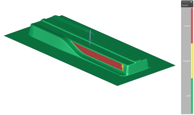
Fig. 1: Backdraft in the drawing tool after springback compensation
During the feasibility phase, design changes are commonplace and still bear minimal consequence. Any necessary partial changes, such as stiffeners for improved robustness or the opening of any wall angles to ensure compensability, should be taken into account at this early phase.
Alternatively, to release the part design, the robustness of the process and compensability of the part with a known method should also be considered.
It’s important to clarify here that the compensability check is not the first step in springback evaluation. The first goal should be to understand which boundary conditions carry the most influence on the resulting springback for the part. This can be realized by calculating springback after each operation and comparing the individual results.
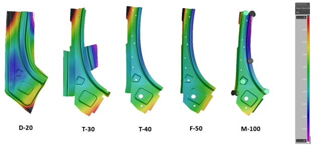
Fig 2: Comparison of springback after each operation
Now, the second step is trying to reduce the amount of springback and guaranteeing process stability (robustness) so the process is easier to control. In an ideal case, this would be achieved such that any compensation of the tools is not necessary.
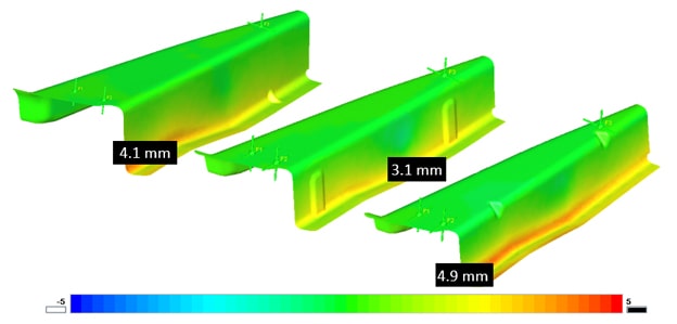
Fig. 3: Investigation of different stiffener options for reduction of springback
The third step is to find an appropriate compensation strategy.
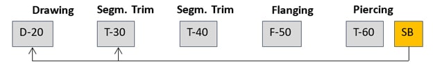
Fig. 4: Compensation of drawing and first trimming operation by springback result of final part, suitable for parts where last operations have only marginal influence on the springback result (e.g., piercing).
Therefore, for the purpose of feasibility investigations, a reduced simulation setup is recommended. This enables us to test out multiple approaches and compare the advantages and shortcomings of each. We can then select the most suitable option based on the data.
Typical characteristics of the setup in the feasibility phase:
- Tool surfaces are created with AutoForm – for quick validation loops of multiple concept designs.
- Closing of cutting tools is not considered (cutting only), i.e., an “optimal” trimming operation without plastic deformation of the sheet is assumed.
- Drawbeads are simulated using a substitute model (adaptive line bead), including flattening to check the draw in and wrinkles during binder closing.
- Scaling of the drawing die influences the springback result significantly and absolutely must be considered.
- Straightforward realization of robustness check uses standards and material files for definition of noise variables.
- Adapted accuracy settings speed up the simulation.
Conclusion
The approach here described how analyzing the springback behavior, process robustness and compensability within the part during the process feasibility phase can make an important contribution to the frontloading strategy in virtual product development.
The original customer who inspired this post was advised by our team to run a robustness analysis to check the repeatability of springback results during part production. Because time was critical, the customer made use of AutoForm’s cloud solution with its high-performance computation capabilities. We analyzed the process, proposed some minor changes and voila – the problem was solved. As a result, our recommendation to conduct additional AutoForm training was approved.
Overall, this approach shortens the development time of a new product and avoids late-stage alterations, thereby improving the overall coordination of development and manufacturing. It’s often the small expenditures that result in great savings.
As for the proof in the pudding? It is through the use of such complete studies that several of our customers have achieved the one-loop tryout. See these two post from Ford and Saitama Japan, who both used digital engineering to get it right the first time around.


?")

