Combining Two AutoForm Solutions to Overcome Surface Defects
[dropcap]I[/dropcap]n this blog post Hisashi Takizawa, Division Manager & Technical Expert of AutoForm Japan, introduces the linked use of AutoForm-ProcessExplorerplus and AutoForm-Sigmaplus, as a means of examining surface defects when designing die faces.
AutoForm is the digital engineering tool for the sheet metal product, and it is the only software designed for a wide range of users from the stamping part designers to the engineers in charge of tryout to use for examination and evaluation of their tasks.
The main feature of AutoForm is that the software can be applied sequentially with every engineering process of the stamping part. For example, during the part design phase, feasibility and yield rate of a stamping can be examined immediately, as soon as 3D CAD data of the stamped part are available.
As for the process planning, not only the stamping layout but also the tooling cost and the piece cost of the stamped part can be examined on a basis of the production plan. And for the die face designers, the forming-related problems, including formability, springback and the surface defect, can be evaluated while examining the countermeasures for such problems.
AutoForm can also be used to examine possible countermeasures when a problem occurs during the tryout with the actual panel, as well as to simulate and examine the problems that may be spotted during the mass production.
The engineering data, as mentioned above, is seamlessly passed onto AutoForm, which enables the users to verify the formability that has been examined by the part designers and the process planners, including the working direction in each process. This leads the die face designers to examine the optimal die face and process conditions. Then, the engineer in charge of the tryout can use AutoForm to verify and examine the specific problems that may happen during the tryout; based on the data now drawn from the previous verification and examination.
At this point I introduce the linked use of AutoForm-ProcessExplorerplus and AutoForm-Sigmaplus, as a means of examining surface defects when designing the die face. Let’s get to it –
About AutoForm-ProcessExplorerplus
AutoForm-ProcessExplorerplus (hereinafter called “PE”) is the core software of AutoForm’s products for specifically defining the tool geometry and the process conditions in each process, based on the information accumulated through the examination of the part design and the process plan, and to run the sheet metal forming simulation. With PE, together with its feature to detect the problems automatically, the user can examine the result evaluation effectively and accurately.
About AutoForm-Sigmaplus
AutoForm-Sigmaplus (hereinafter called “Sigma”) is an additional software that comes together by default with the PE from R7, the latest version of AutoForm, on. This software is used to examine any proposed countermeasures to possible problems, and also to simulate problems that may occur during the mass production.
Concerning the examination of those countermeasures, the user first enters the variation of “controllable” tool and process conditions, such as the punch radius, bead geometry, and the blank shape, which potentially might solve the problems and runs the forming simulation that calculates all the variations of these process conditions. Then the user can dig out the effective countermeasures by verifying the conditions, with which the problems are dismissed, and the optimal values, as well as the safe-ranges where the problems do not occur.
About Those Problems during Mass Production
When aiming to correct any problems that may occur during mass production, the user first enters the variation of “uncontrollable” process conditions that can be observed during the actual mass production, such as the thickness and other properties of the blank material, the cushion-force, and the lubrication. Then the user runs the simulation to verify the occurrence rate of the problems, such as cracks, wrinkles, springback and surface defects. With this, the user can examine the process conditions that should be managed during the mass production to ensure a robust manufacturing process and significantly reduce part scrap rates and production down times.
A ‘How-To’ for Examining Surface Defect Countermeasures
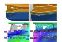
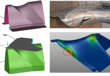
One procedure to examine the countermeasures for surface defects during the draw operation is as follows. Looking below at Fig. 1, the result of the draw simulation shows good conditions, without cracks and wrinkles inside of the product face, in terms of the distribution of the formability and possible cracks. However, in terms of surface defects, Fig. 2 below shows an occurrence of a surface defect at the rear of the turn signal recess.

Fig. 1 (left) Distribution of the formability, (right) Possible cracks (max failure)

Fig. 2 Surface defects (attention on the product geometry)
Various kinds of countermeasures can be taken for the surface defect, however, for this blog post let’s focus on the adjustment of the drawbead, and the modification of the tool surface around the part where the surface defect is found.
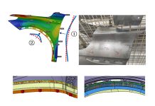
With Sigma, the adjustment of the bead height and the modification of the tool face using the morphing feature can be examined. As for the modification of the tool face using the morphing feature, the geometry modification feature in AutoForm, as shown in Fig. 3, is used to modify the face around the area where the problem occurs, by moving the curved geometry up and down in the normal direction.

Fig. 3 The part where the draw tool face is modified
With Sigma, the curves to control the morphing (blue lines) are set on the tool face where the surface defect occurs (as shown with the dotted line in the figure) and displaced with varying distances inside and outside of the vehicle. Further, the restraining forces of the drawbeads will be adjusted by defining value ranges. Based on the input, the AutoForm forming simulation is run with multiple value combinations for the adjustment of drawbeads and for the modification of tool face geometry. Fig. 4 shows the problems with regards to surface defect, that are found automatically from all the calculation results using AutoForm Sigma.

Fig. 4 The result for problems on the surface defect
It must be noted that Fig. 4 shows additional surface defects which could not be identified with the initial conditions – indicating that with slightly changing boundary conditions additional areas with surface quality problems will occur.

Fig. 5 The result with which Sigma is used
to apply the optimal countermeasure for the surface defect
With Sigma, every combination of these conditions is examined in order to find the optimal value to dismiss the surface defect effectively. Fig. 5 clearly shows that all issues on the surface defects could be resolved. As shown in Fig. 6, Sigma also indicates that the modification in the tool face geometry (MCZT and MCZT2 represent the morphing lines variation) is more effective than adjusting the drawbeads (reSt2, reSt3, reSt4) under these conditions. In this case, no problems with surface defects occur. Besides, as shown in Fig. 7, the possible other problems including the cracks and wrinkles can also be checked, and Sigma shows no problem at the same time.

Fig. 6 The degree of influence for each countermeasure

Fig. 7 The result on cracks (left) and wrinkles (right)
Conclusion
As for the examination of the countermeasures for the surface defect, Sigma is run to examine the adjustment of the drawbeads and the modification of the tool face geometry, and the optimal conditions are then found successfully. Sigma with its unique features comes together with the ProcessExplorer of the latest version, AutoForm R7, so a wide variety of users can have access to it.
With Sigma, the users can run the examination on not only the surface defect but also on the cracks and wrinkles, as well as on minimizing the springback.
Please contact us if you are interested in Sigma and its further application, and don’t forget to sign up to our blog to get blog-post updates to your inbox.


