Do you ever think about the numerous options for draw bead modelling?
- When and why should we use numerical line beads?
- When is it best to use mesh bead geometry?
- Is there a way to benefit from both?
To achieve the best forming process, control of material flow during the drawing operation is required. Often, drawbeads will be used to control material flow. The combination of the drawbead and the applied binder force restrains the flow of blank material, forces stretching, limits wrinkling, and affects panel quality. When drawbeads are called for, work is needed to optimize their location and shape. In most cases, this follows the rules defined in company standards or in given manufacturing constraints. Since the shape of the blank and resulting drawn-in sheet is governed by the drawbead design, the outcome of the drawing operation is required for the verification of estimated material costs and the planning of secondary operations—especially to predict the springback behavior of the final part after trimming.

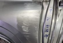
Outer sheet metal Draw-OP engineering relies on drawbeads to achieve stretch requirements for quality stamping
One way to describe the draw bead is to generate appropriate geometries in CAD, import them, mesh those surfaces, and include them in the computation of the forming analysis. The tool surfaces, including the drawbead design, result in a comparably fine mesh consisting of a large number of elements for Finite Element Analysis (FEA). Deformation of the sheet metal, including the bead geometry and other process parameters, is simulated and analyzed for its effect. If the results are poor, changes to bead geometry may be needed—updating the shapes, reimporting, then rerunning the simulation. After several iterations, it may become clear that these changes are inefficient. Even with parameterized drawbead 3-D modeling, there is still a lot of repetitive export, import, and redefinition of model components, as well as significant computational load, to simulate the bead geometry in FEA.
Simulating the material sliding through the meshed drawbeads generates the stretching restraint to the sheet and the reaction forces as metal bends and unbends. However, the computation of 3-D beads is linked to significant disadvantages, such as massive increase in number of elements in the mesh, high memory utilization, increased CPU-time, and the stack up of any computational inaccuracies, associated with very small meshes. In areas of small radii, deformation of the sheet and the bead influence might be missed during analysis. To avoid overlooking small radii, much finer meshes and shorter time-steps would be required to simulate the draw beads accurately, resulting in increased load on computing resources.
For these reasons, many apply bead geometry only during final validation and use numerical methods for Process Engineering. Metal forming analysis programs have implemented numerical “line bead” models, which enable the user to define a factor or proposed bead profile shape for blank restraint. This allows the user to import only the tool surfaces, without the draw bead geometry, and later define draw bead parametrically. Recent innovations introduced line bead models that relate user-defined profile shapes of beads to the restraint of the material through that shape. This way, the modification of the draw bead geometry becomes convenient and fast. Each iteration can be easily modified to apply more or less force without the requirement of further 3-D CAD modelling, making line beads preferable when designing and evaluating drawing processes.
A state-of-the-art solution is the employment of advanced line bead models that use current process conditions to calculate draw bead effects: the Adaptive Line Bead. Unlike in other line bead models, corresponding draw bead restraint and uplift forces are continually calculated during the simulation. Therefore, the sheet metal held within the draw bead geometry, as influenced by the current gap between the tools, is considered. The current thickness and bending strains of the sheet within the draw bead and the adjacent tool areas are also computed. Local properties, like induced work hardening effects in the sheet before entering the considered tool area, are fully considered for the computation of restraining forces that the material generates in the bead.

Geometric beads required significantly more elements to compute
The setup of this bead modelling approach is convenient and fast. Dialogue boxes support the definition of the drawbead center line and profile of bead by selecting bead type and geometry parameters. No specific definition of any further computational settings or finite element analysis constraints are needed to obtain high-quality simulation results that match reality and are comparable to the geometrical bead modelling approach.
One limiting factor for the use of line beads has been the appropriate modelling of sheet metal behavior during the setting of the draw bead shape in the blank. The amount of the blank material used to form the beads themselves might be underestimated, and the effect of the beads on panel “breakdown” might be missed. During closure of a binder with draw beads, material not already held by the die may deform differently depending on the bead geometry included during forming. Distortion during the binder closing material may adversely affect the forming process; this is one fact that supports the use of CAD-modeled geometry instead of numerical line beads.

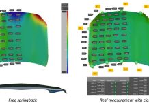
Hood outer “binder wrap” without 3-D drawbead geometry
To capture the effects of the bead geometry during closing and after opening of the draw die, line bead technology needed to be enhanced to recognize the effect of forming the proposed bead section into the blank and to capture the effect that the deformed bead shape has on the finished panel. The adaptive line bead profile, that automatically modelled the bead mesh, along with a very novel “flattening” and “unflattening” functionality, was used to combine the advantages of geometric draw beads and the line bead models.”

Hood outer “binder wrap” with material deformation as result of inclusion of 3-D bead profile during closing

Localized buckling in the material adjacent to the formed beads will behave differently during Draw-OP
Geometric draw beads are used for binder closing when the compute time is short and the mesh is still mostly flat. The deformation of the blank caused by the forming of bead shape is fully captured during the binder closing, wrinkles in the unsupported sheet area. Then the mesh in the bead area is flattened and an appropriate line bead restraint is applied during the drawing process. State variables are mapped to the affected elements in the bead zone. After the flattening, the draw bead centerline will be used as the numerical line bead; therefore appropriate uplift and restraining factors will be applied. Throughout the forming process, the effective restraint of the proposed bead geometry is applied to the affected elements, and material behaves as if the flattened sheet were deforming through the bead shape.
After completion of the drawing operation, an “unflattening” reinstates the deformation in the mesh caused by geometrical beads. During unflattening, state variables are mapped to the newly created elements in the area of the draw bead. This geometry and its behavior are suitable for qualitative analysis of the influence of deformed binder material and the bead shape on springback behavior.
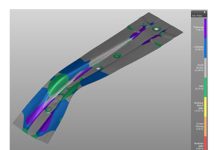
A review of a real cross-member has validated the concept of using geometric beads with flattening and unflattening. Failure predictions for splitting and wrinkling failure yielded the same results and thickness strains measured in the simulation and are nearly identical to the performance of the real stamping. When compared to the results using geometric beads through the entire forming process and estimations made with the AutoForm adaptive line bead with flattening, we find that the results were nearly indistinguishable. The adaptive line bead predicted perhaps slightly elevated thinning predictions—more conservative for engineering.

Comparison of cross-member analysis results, with 3-D geometric beads (blue) and Adaptive Line Beads (orange)
Detected differences in the results proved so small that they did not affect the method planner’s decision-making process. Behavior of the material within the bead area and adjacent material and the prediction of safety or failure of the part showed no benefit when the geometric bead was included. However, the computational burden of the geometric bead is significantly higher: For the shown symmetrically modeled cross-member, nearly one hour of CPU-time is required to solve the geometric bead while only 13 minutes of CPU-time is required to solve the model that employed flattening and unflattening with the adaptive line bead.
The adaptive line bead delivers all the needed predictions for metal flow restraint, strain states, tooling forces, and springback shape of the binder surfaces, when used in conjunction with flattening and unflattening. In conclusion, the benefit of using the 3-D geometric beads during closing and the springback behavior of the formed bead can be realized at a fraction of the computer or solver license requirement.


