
Galling is a phenomenon in sheet metal forming, where the frictional force abruptly increases under specific conditions at the contact surface due to microscopic welding. Galling between tool and sheet leads to a sharp increase in forming force, fatal damage to the product surface, and severe wear of the tools — affecting not only the part quality but also the success rate of the stamping operation. During try-out, even if only mild galling appears on the tool surfaces, it is critical to address it before rapid wear sets in. 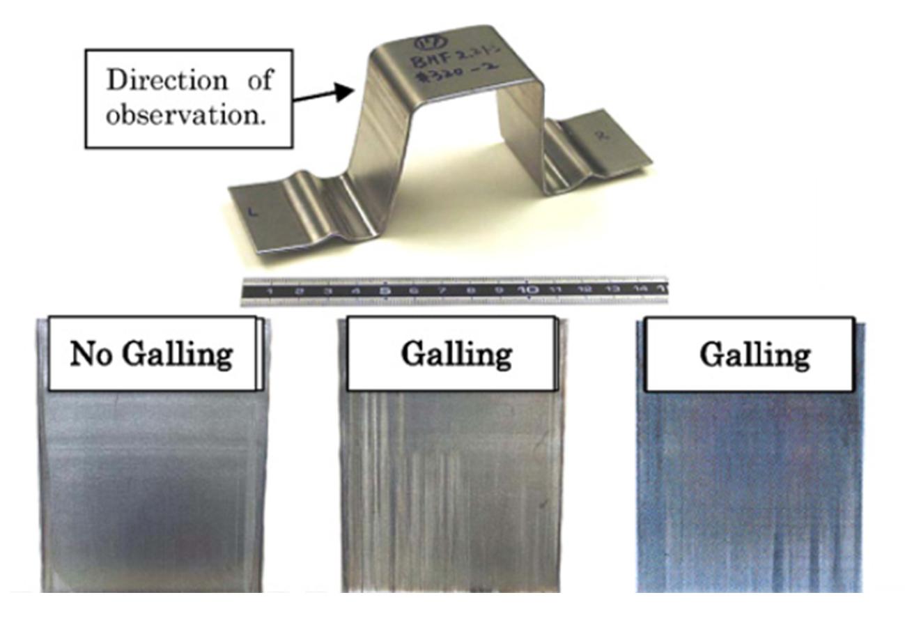
Fig. 1. Optical photograph of sheet surface quality after bending test
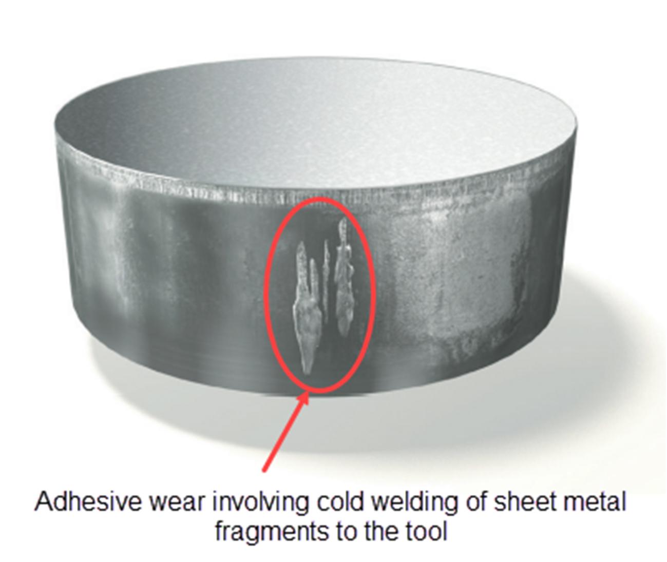
Fig. 2. Galling on a tool (punch)
I was working with an automotive OEM last year to help resolve a galling issue they were facing on a tailgate outer part. The sheet material was CR04, 0.9 mm thick, and the tools were made of cast iron. When the parts were stamped in try-out, the formed parts showed a very bad surface finish in some areas and the tools showed adhesive wear due to the micro-welding of the sheet metal on the tool surfaces. From their previous experience, this OEM clearly identified a galling phenomenon. Since the tools were already manufactured, they had limited options to prevent galling. Some measures they took included increasing the amount of lubrication, polishing the tool surfaces, and trying a different sheet material coating. However, none of these workarounds significantly reduced the galling effect. Finally, the OEM decided to alter the bead design setup. Since this class A tailgate part did not have sufficient draw depth, they were required to use deeper beads to achieve optimum stretch on the panel. The taller bead setup was the major contributor to galling in this case, which they similarly observed on some of their older parts. They were confident that changing the single bead design to a shallower double bead design would likely resolve the galling issue without compromising the stretch/plastic strain, as they had used that approach with success in the past. The last step in this process was to re-engineer the die design to come up with new optimized double beads, before re-cutting the tools. Instead of employing the traditional trial and error approach to modify the bead design, the OEM took advantage of AutoForm Sigma to improve the process systematically. The new (second) bead had to be 25 mm away from the existing bead and in order to identify the optimum bead height and groove radius, they implemented an AF reduction strategy in the simulation, as shown in Fig. 3. It was crucial to generate good formability and plastic strain conditions (possibly unchanged) to produce a defect-free panel; with that goal in mind, it would have taken multiple trials to modify the beads manually. In addition, the blank shape was optimized using the same approach and the blank size was increased slightly to accommodate double beads. 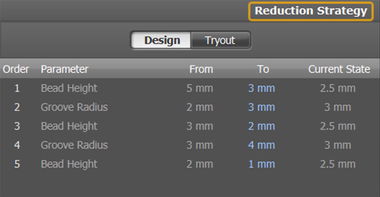
Fig. 3. AutoForm Drawbead Reduction Strategy
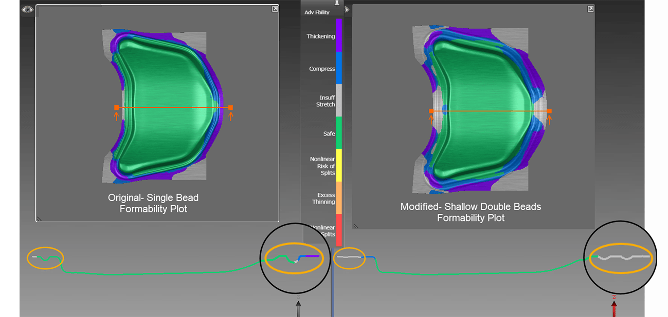
Fig. 4. Single Bead vs Double Beads Formability Plot
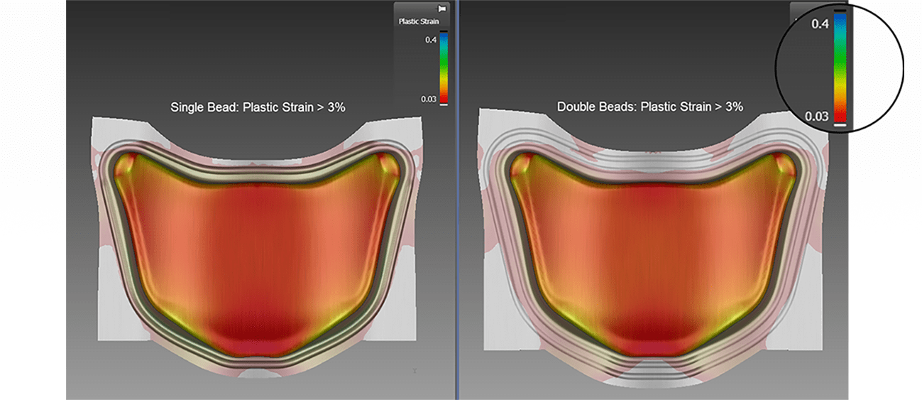
Fig. 5. Single Bead vs Double Beads Plastic Strain Plot
Owing to issues of confidentiality, the OEM’s simulation results cannot be shared on this blog. Instead, a similar approach was performed on a non-confidential hood outer panel, the formability results and plastic strain plot of which are shown in Fig. 4 and Fig. 5, respectively. The simulation on the right with double beads and a slightly bigger blank considerably resembles the simulation on the left, featuring a single bead setup. The OEM established similar simulation results on their tailgate outer part using AutoForm’s systematic process improvement technique without too much time spent in the re-engineering phase. Later, the tools were re-cut to attune the double beads and the galling had reduced significantly. Lastly, with some minor adjustments to the press conditions in try-out, they were able to eliminate galling on this panel.


?")


