
SAIC General Motors China Shares Case Study for the New Malibu Hood
I
n this blog post, Wang Jian from SGM China shares his experience after receiving the delivery of an outer hood tool in an extremely bad state. Due to an earthquake, their Japanese tool supplier was forced to ship the tool set way ahead of schedule without full process simulations during engineering and sufficient time for springback compensation in tryout. On the other side of the ocean, this was the Chinese tryout team’s first case with aluminum panels! This case study reveals the recovery plan by three measures.
Introduction
In this post, we will talk about lightweighting with aluminum, and the problem of springback. Aluminum has the advantages of being low density, lightweight, recyclable, energy saving, and environmentally friendly. The metal finds a new use as rolled aluminum sheets are now being utilized in vehicle outer panels. OEMs in the US, Europe, and elsewhere have used aluminum for many of the body panel parts, and have even developed an aluminum vehicle body (see Figure 1).
However, the aluminum sheet has inferior elongation and an elastic modulus that is only 1/3 of its steel counterpart, which results in far more springback. Therefore, quality control is more difficult than for steel. In addition, due to relatively low hardness, defects in aluminum parts arise easily, such as tiny scratches, impact lines, wrinkles, cracks etc. Generally, aluminum causes a variety of technical problems.
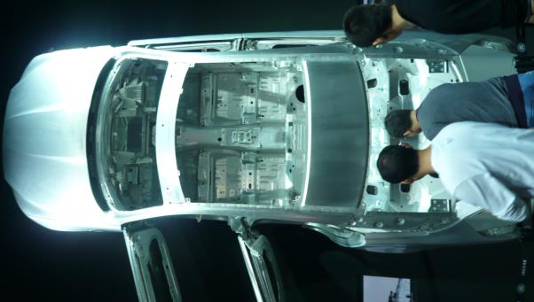
Fig.1 Aluminum Body in Auto Show
SGM’s Malibu: Hood Springback
A Japanese supplier, overconfident about their tryout ability, neglected the full process simulation in the early process design stage. Even worse, the die was shipped to SGM ahead of schedule because of an unexpected earthquake in Japan. These combined factors led to terrible dimensional quality, which caused a challenging problem downstream for SGM’s stamping project team.
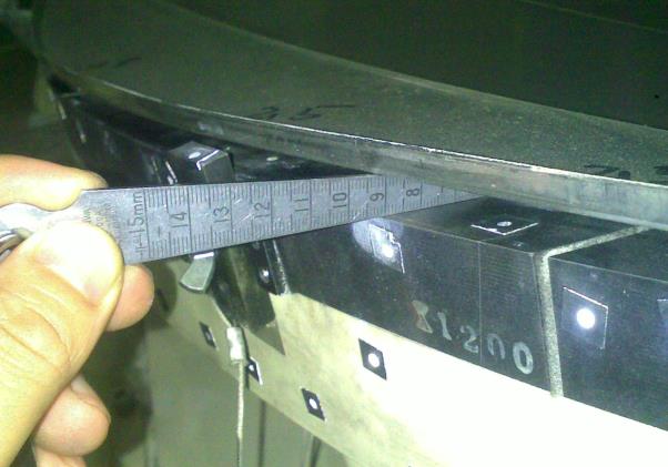
Fig.2 Springback of Actual Panel
Software Simulation
SGM employed AutoForm to implement full process simulation using the die vendor’s stamping process with a typical Final Validation (FV) setting. The simulation results displayed strong agreement with the stamping results. This provided a solid foundation for further troubleshooting and gave us confidence in how to proceed.
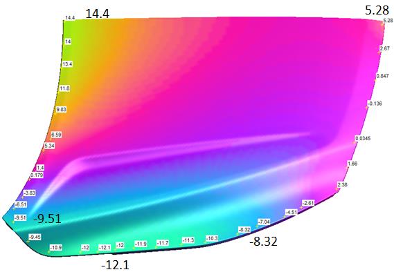
Fig.3 Initial Springback Simulation Result
According to the figure above, the springback varies from -12.1mm to 14.4mm, which is highly problematic. Worse still, the springback directions are not identical.
Searching for Solutions
Interestingly, tryout members of the press shop only had previous experience with steel and had never worked with aluminum, which made it especially hard to predict springback. Therefore, we decided to first obtain a CAE result and then determine a hands-on measure that corresponded to the CAE result. After several rounds of technical discussions, we came up with more than ten optimizing plans. Although it was impossible to physically try all these plans out in the press shop, we could easily verify them using virtual simulations.
Additionally, due to the magnitude of the springback, direct compensation was not advisable so we tried first to reduce the quantity. Three of the most effective optimizing plans are shown here:
Plan 1: Reduce the springback by adjusting the timing of the flanging operations.
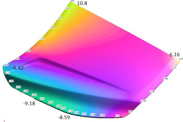
Fig.4 Sim results after timing change
As shown, a slight improvement was observed. Because this plan could easily be physically implemented in the die building, it was carried out in the press shop.
Plan 2: Add drop-shaped material gainers along the windshield area to reduce the stretch-stress during flanging.
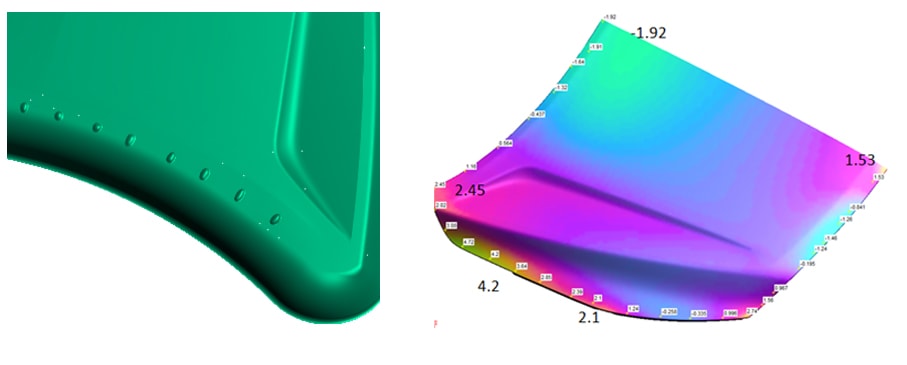
Fig. 5 Left – Drop-shaped material gainers model in simulation.
Right – Result After adding drop-shaped gainers.
It can be seen that the panel’s springback experienced a dramatic change, as expected. This showed that the drop-shaped material gainers had a substantial effect, which was verified in later tryouts. A further advantage was that this plan could be easily implemented.
After a number of correction loops, the overall springback was sufficiently controlled, except for the local areas near the head lamps. These areas were still a little lower than nominal height, which resulted in up to 1.5mm deviation from the hood assembly’s dimensions. To solve this problem, we decided to make the draw die shape closer to the finished part by adding localized steps. Using this method, we could improve the local dimension quality.
Plan 3: Modify the draw die design locally, as shown in Fig.6, with results shown on the right.
To apply the local stretch and increase stiffness, we modified the addendum area of the drawing die. Fig. 6 shows the initial shape of the addendum on the left while the middle image shows the new step we introduced.
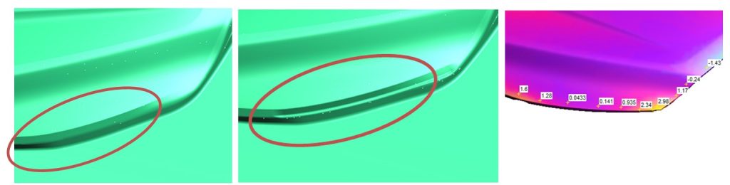
Fig. 6 Initial Draw Die (Left), Modified Draw Die with Step (Middle), Springback Improvement with its modification (Right).
As seen, the springback value of this area is now within tolerance.
Although compensation remains the most direct way of tackling springback, when the magnitude is too high, it first needs to be reduced. The hood outer is a skin panel which demands high surface quality requirements. In this situation, compensation is the last measure we would like to take, rather starting with other low-risk correcting methods.
Tryout & Follow up
Once the die was put into mass production, the actual state closely resembles the CAE results, as shown by Fig.7 and Fig.8.
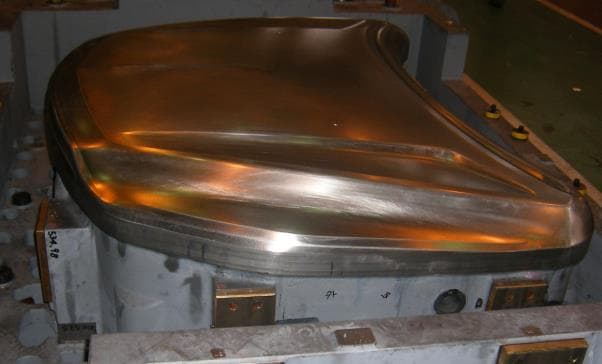
Fig. 7 Initial Drawing Die Model
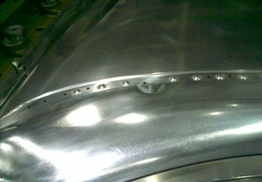
Fig. 8 Drop shaped gainers in drawing die
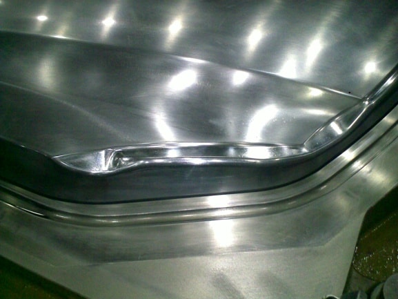
Fig.9 Modify Drawing Die Surface
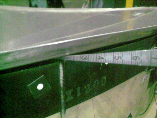
Fig.10 Hood Outer Final Dimension
According to Fig.10, the dimensions under the free springback state were all controlled within +/-2mm. Although the +/-0.5mm requirement had not been met, we decided not to “over engineer” the hood outer, since it would be coupled with the inner part and we were confident that the final assembly dimension could be assured by controlling the inner panel dimension and adjusting the roll hemming process.
Conclusions
With lightweighting on the rise, the use of aluminum sheets is also increasing. Thus, aluminum is a considerable issue that the entire industry will have to confront. Meanwhile, rapid progress in computer technology and software has significantly enhanced the accuracy of CAE, providing an excellent simulation tool. By implementing CAE analysis before die machining, many potential issues can be avoided and thus cost and delivery of parts can also be better assured.

Fig.11 SGM Chevrolet Malibu
Wang Jian,
Die Process Manager, SAIC General Motors
Jian Wang, SGM, Die Process Manager, Research direction: Auto manufacturing technology E-mail: jiann_wang@saic-gm.com
Further Reading:
[1] Shiguang Hu, Hezheng Chen. Engineering explanation of metal sheet cold forming [M]. Beihang University Press 2004.7.
[2] Shuoben Li. Stamping technology [M]. Mechanical Industry Press, 1982.


?")


