
We have heard the following questions countless times: How should I set up my simulation? How do I process this part? The simple answer is that you need to set up your simulation to accurately represent your production/manufacturing process. Of course, engineers may not always be entirely sure how to mimic their production process correctly. We recommend a process approach as the guiding force to build a truly accurate model.
You may wish to read our related post, “How Can You Prove Accuracy in Sheet Metal Simulation? The Principle of the Accuracy Footprint Unveiled.”
All formability engineers should understand that the finite element method exists solely in a perfect universe. It is a complex series of mathematical equations that, when used properly, still produce a result that does not account for all the design and noise variables inherent in all manufacturing processes. Unfortunately, manufacturing practices do not exist in a perfect universe; they exist in flat-roll steel mills, die shops, and stamping plants. There are hundreds of intrinsic design and noise variances that will influence the production panel and cause some discrepancies between simulation and actual tool stamping. With that said, we will summarize the following key process steps that you should take, regardless of the software you are using:
1.Understand what’s in your toolbox- Although most formability engineers make this look quite simple, there is a lot of tribal knowledge involved in the areas of draw developments, die processing, fixture design, material behavior, and sheet metal theory. Applying this knowledge can enhance a user’s ability to best represent the intended manufacturing process. For best results, familiarize yourself with the front end and back end of the software you are using. Beyond your base application knowledge, you should consider training in advanced application knowledge, such as compensator, systematic process improvement and robustness to enhance your opportunity for success. These are the key ingredients to successfully model and evaluate the process and simulation results
2. Collaborate on the shop floor- Perhaps the most important point we will make in this article is to collaborate, collaborate, and collaborate. Why? Because no company will fully benefit from the powerful tools available unless their team is pulling the proverbial rope in the same direction. Yes, your engineering team must have a solid understanding of the die tryout department’s daily operations. Similarly, die tryout needs to recognize the hundreds and hundreds of man-hours it takes to simulate a part. We as simulation engineers have worked countless hours on developing and reworking the die face geometries, calculating robustness studies, and compensating surfaces. All of that is performed to help streamline the non-value-added hours spent in die tryout. Ultimately, we need to collaborate more effectively with our die tryout departments. We all need to share a common understanding of the effect of taking a grinder to the dies. Simple tweaks like working draw beads or moving a blank can affect strain rates and consequently, springback. We should urge our teams to meet and educate each other on common practices and subsequent countermeasures. Once shared ownership has been established, the company as a whole will benefit. AutoForm has developed TryoutAssistant to help the tryout department make decisions based on cause and effect results.
3. Recognize that “evolution” inherently means change- As technology changes, we must adapt accordingly. In the simulation world, traditional practices may no longer be the most effective. We need to realize that the software has evolved and embrace the progress that developers have made. By recognizing the changes, testing the software, and adapting our processes, we can leverage the benefits of technological advances. To illustrate with a simple example: a conservative material card (which was commonplace 20 years ago) should not be substituted for a material card that accurately represents the actual material.
4. Set up your simulation to accurately reflect the intended manufacturing process, always in a detailed and consistent manner- AutoForm promotes a left to right, top to bottom approach; as such, the user should do the same. Not only does the user have to consistently define a process, but all the parts should be processed in a consistent format. Only then will your company be in a position to benchmark and run correlation studies.
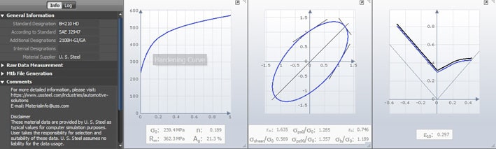
5. Accurately represent your material– Paying the average cost of $175.00 for a single tensile test is the best money your company will ever spend. From this data, you can generate representative materials as opposed to using the inherently conservative material cards.
6. Model your tool kinematics accurately– Verify that the binder start height of your tool is positioned properly to avoid any punch interference. Similarly, ensure that the blank holder travel and forces are attainable (within the capabilities of your press), the blank is positioned and gauged properly, the gravity effect of the blank is performing accurately, and the blank holder tonnage falls within the press tonnage curve limitations.
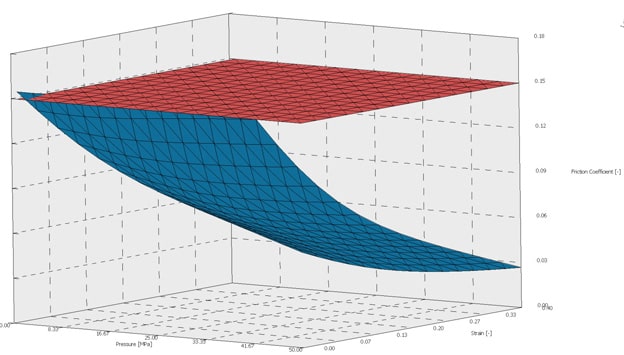
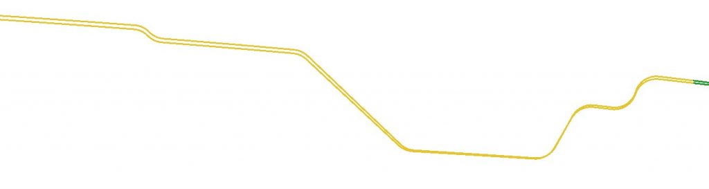
7. Model your friction- As an industry standard, most users model the coefficient of friction (Coulomb (μ=.15)) for steel as a constant. Recent developments in tribology with software such as TriboForm have established a more accurate coefficient of friction based on the interplay of tool material and its surface finish, sheet steel and its surface finish, amount of lubrication, contact pressure, and forming velocity. As you can see in the figure below, the tested friction model experiences a substantial decrease in the coefficient of friction (blue) when pressure and strain increase. This tells us that the Coulomb (μ=.15) coefficient of friction (red) provides more conservative results as they pertain to formability and thinning.
8. Minimize your blank and understand the grain direction– Perhaps the most valuable tool in your AutoForm interface interface is the blank nesting and embedding function because it identifies your material utilization. This tool alone can identify several millions of dollars per year in waste.
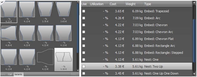
Possible blank die configurations based on your defined blank. Using these configurations, AutoForm can calculate the cost per blank and effective utilization.
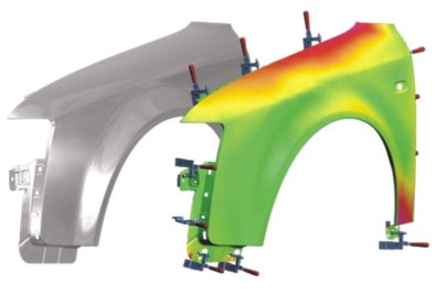
9. Set up your measurement operations to reflect the panel on the checking fixture (orientation, datum surfaces, clamps, and gauge pins)- Gravity will have a heavy influence on stamping, from a fixture in the vehicle position to a fixture designed 90o to the vehicle position.
10. Optimize your geometry to make your formability acceptable to your corporate standards- If you don’t care to optimize your geometries, you can utilize AutoForm Sigma, a systematic process improvement tool that will help you to simulate multiple iterations based on the design variables you identify as key influencers. You will then have the ability to extract and spin-off the optimized solution.
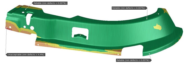
11. Using AutoForm Sigma, validate the robustness (Cp) of your virtual process- If the virtual die process isn’t capable of being robust (Cp <1.67), why would we build a million-dollar set of tools that will merely produce the same results? We can achieve this through process changes, product changes, or potential changes to the draw development. Remember, if we have Cp <1.67, it is very unlikely that any changes made to the surfaces will pass the process capability index (Cpk).
12. Compensate your geometries using AutoForm Compensator. Evaluate your 3D surfaces for quality to ensure they have met your corporate expectations before you generate NC machine files.
Revalidate your compensated geometry through the entire simulation process.
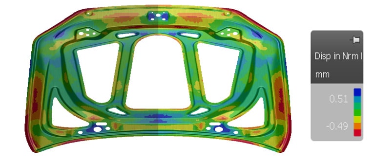
13. Revalidate your process capability (Cp) and process capability index (Cpk)– We trust that most of you have seen a CMM report at die buyoff milestones. The Cp and Cpk must be >1.67 to put your company in a position to sell the dies. AutoForm can provide these statistics based on all the noise variables defined by your standard.
14. Integrate simulation-based thinking with the process approach- Formability engineers have been increasingly expected to take responsibility for risk and opportunities. Moreover, the growing use of digitalization in departments enables engineers to give assurance that the digital quality system can achieve the desired results, as well as prevent or reduce failures during production, for consistent improvement. As a result, the simulation engineers will eventually take on the primary role of establishing a proven and accurate quality assurance system for other departments. If companies take a similar process approach, based on the AutoForm Accuracy Footprint, the above outlined process steps automatically and systematically fulfill the responsibility of identifying risk and opportunities. This is because the final revalidated, robustness-analyzed digital design has passed the risk criteria of the quality control boundary and its opportunities have been verified through the entire engineering process chain. As a result, new responsibilities will mean less work.


?")


