
The Final Touches to Secure the Highest Level of Simulation Accuracy
This is part six and the final installment ofour series on using the AutoForm Pareto Principle to improve simulation accuracy. In this post, we examine tribology and contact pressure as the two remaining parameters to complete our simulation accuracy footprint.
Series Index: Part 1, Part 2, Part 3, Part 4, Part 5, Part 6
As mentioned in our previous posts, the Pareto Principle is based on the premise that the successive parameters contribute less to simulation accuracy. In other words, the essential parameters must be defined first, followed by the crucial parameters, and ending with the important parameters. By properly defining and validating these three groups, we already have an accurate and precise simulation model as they comprise 95% of the total simulation accuracy. This means that the simulation result will be highly representative of the future production reality. Now that we’ve reached the final stage, we’re focused on defining the detailed parameters and securing the last 5% accuracy to create a perfect digital prototype.
After evolving beyond the fundamental aspects of the accuracy footprint, we’ve moved on to ironing out the finer details. Yet, we must keep in mind that while the detailed parameters contribute very little to overall accuracy, they make it very challenging to obtain a precise and verifiable match between the simulation and reality.
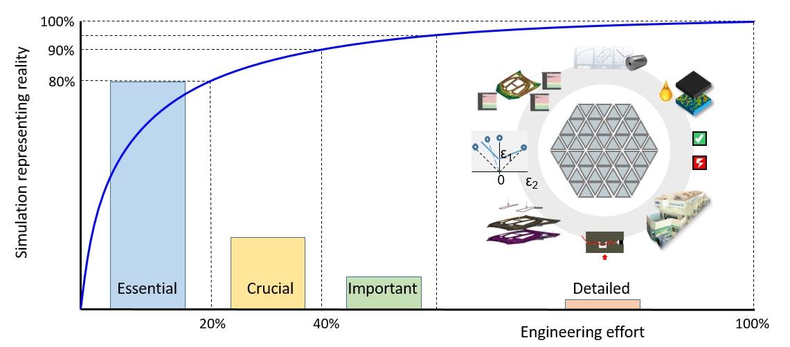
Fig. 1: Our Pareto diagram has reached the final detailed input phase
We have two different types of detailed parameters: tribological and contact pressure conditions.
Tribology Related Parameters
The tribology related parameters include tool surface roughness, polishing, sheet surface roughness, the amount of lubricant, temperature variation, and ram velocity profile. The features incorporated into the simulation should be quantifiable at the time of engineering and those definitions should be reflected precisely in reality —otherwise, we won’t have a true digital twin model of the process.
As an example, the tool surface roughness influences the tribology system. One of the crucial parameters defined during engineering was the tribology model, based on an applied standard. The tool surface roughness might have an RA of around 0.6 micrometers, providing the assumption that during tool manufacturing and tool polishing, this roughness value will be achieved on the physical tool surface.
Deviations from the standard can be taken into account, such as when the tool surface roughness is 0.9 micrometers because the tool wasn’t polished enough or this value was deemed“good enough”. This detailed parameter can be modified in TriboForm, an advanced friction modelling solution, which can also perform a validation simulation of the setup. However, with the validation occurring after the engineering phase, it will therefore not increase the simulation accuracy.
The basis for the modification is a measurement of the actual tool’s surface roughness. This kind of “post-simulation validation” is often applied in the event of an unexpected deviation between simulation and reality. However, to install a digital process chain with maximum efficiency (to minimize tryout effort, for example), the focus should be ensuring that the actual tool accurately reflects the simulation. This doesn’t mean adjusting the simulation to reflect reality in case deviations occur when using the simulation model as the digital master. Ultimately, for an efficient engineering process, we must properly transfer the applied standards and boundary conditions from engineering to reality.
Similar validation studies are sometimes performed with respect to other tribology-related parameters, such as the sheet surface roughness, the amount of lubricant, temperature variations, and the ram velocity profile. These parameters can be defined in detail during the simulation setup. Modifications of these values will generally cause very minor changes to the results. However, these modifications must be based on the physical process parameters, which can only be measured at a very late stage —after the engineering work has been completed. From an engineering point of view, there’s little value to be gained here.
In the event the parameters cannot be controlled as precisely as required, they should be included in the robustness analysis to gauge their impact on process sensitivity. The goal is to validate whether a change in these parameters results only in a minor variation of the results, fulfilling the requirements of the process capabilities. To that end, parameter variation is taken into account to guarantee a proper process window that will still work even without a precise process point description.
Contact Pressure Related Parameters
The second set of detailed parameters includes tool crowning, 3D tool design, tool deformation, press bed deformation, tool spotting, tool shimming, and tilting. All of these contact pressure-related parameters are strongly correlated and influenced by many different factors, such as 3D tool design standards, tryout process procedures, press construction— even the maintenance status of the press.
None of these parameters can be considered alone owing to their strong correlation. We must consider how the tools are crowned, since the complete tool and press bed bend under load along with the total deflection all depend on the 3D tool design and the rib design, affecting tool stiffness. The resulting load and its local force acting within the tool depends on the tool spotting (i.e., the actual contact areas transmitting the forces) — which in turn is influenced by tool crowning, tool deformation, and the press bed deformation. The parameters considered in this group form an intricate and complex system of interdependent physical phenomena.
Tool crowning is applied to compensate for the tool and press bed deformation, neutralizing the effects of tool and press deformations. With this in mind, two strategies emerge to properly simulate this behavior. The first simulation strategy does not include the tool crowning, tool deformation, or bed deformation, since this setup represents the nominal tool definition and these three effects are designed to compensate each other. The alternative simulation strategy takes all of these aspects into account. This strategy has the disadvantage that all relevant details must be defined in the engineering or model building phase. As explained above, this includes details regarding the applied 3D tool design standards and press bed stiffness, the overall tool stiffness, the exact amount of crowning, as well as the spotting strategy used during tool tryout. If some of these details are unknown during engineering, the first strategy is the best way forward.
Similar to the tribology-related parameters, we incorporate all the contact-related details to validate the process, ensuring it fits an effective engineering workflow. Accounting for these parameters and effects requires significant effort. On top of that, they are only available once the 3D tool design exists and the tryout and production press have been defined. While these effects exist, they should have a limited impact on the final result if the production process was well designed. An understanding of the real stamping process should be applied to overcome the negative influence of these parameters, as indicated by the simulation. The informed engineer can primarily circumvent any unwanted deformation and overcome the problems arising from contact-related parameters by aligning the stiffness of the3D tool design with the acting forces.
The interaction of all contact pressure related parameters also forms the tryout playground. Tool spotting is the driving force for the resulting contact pressure, which in turn defines the local forces and the resultant force on the tool. Carefully spotting the tool is the main lever to control the overall deflection of both the tool and the press bed. The boundary conditions are defined by the process setup and 3D tool design. Taking a holistic approach with respect to contact pressure-related parameters will determine a successful tool trial. To that end, tryout activities do not account for isolated parameters — rather, they are considered as part of a complex system.
This concludes the last leg in our journey through the exciting world of AutoForm’s Pareto Principle in simulation accuracy. We started with the essential parameters, followed by the crucial parameters and important parameters. This stepwise approach results in a highly accurate simulation model, yielding a representative prediction of the future production reality. Including every minor detail is a poor trade-off regarding engineering effort versus simulation accuracy, since modelling effort is extremely high but accuracy gains are relatively low.
In this last entry, we demonstrated that certain details only become known very late in the engineering process; they are also strongly correlated and require a lot of effort to match in reality. Moreover, these detailed parameters only effectively contribute to the accuracy if the simulation base is well defined.
Looking at the evolution of the simulation model, our primary takeaway is that any consideration of less significant parameters only makes sense after ALL parameters of greater importance have been secured.
This approach has two very important consequences: first, the model building process needs to strictly follow the parameter families from most to least significant. That way, we define a clear, consistent, and efficient model-building process that works every time! The result is an easy-to-use model building strategy independent of the object of the analysis. This is a very useful insight for many users of forming simulation software. The other important consequence is that if a parameter of higher significance needs to be changed during the engineering process (owing, for example, to new information about the part or process), then ALL parameters of less significance need to be re-evaluated to ensure they still make sense and are consistent with the more important parameter that was just altered.
We hope you find this contribution useful, as it was designed to make the lives of process engineers a little easier. Your experiences, comments and remarks are highly appreciated.


?")


