
Growing demand within the automotive industry for weight reduction and increased vehicle safety requires the use of structural components manufactured with steels of high mechanical strength [1]. New steel alloys have been created to meet these new challenges and several have already become standard throughout the automotive industry. Among them, the steel USIBOR1500 was developed with the aim of improving the production and performance of structural parts and high-strength reinforcements through the use of hot stamping technology [2]. Equipment such as presses and tooling must be radically changed, in addition to introducing new elements such as furnaces, cooling systems and handling facilities. All of the elements must work harmoniously together to achieve the desired geometry and properties in the final part.
In the direct hot stamping process, the sheet is heated to a temperature of around 950°C or until it is completely austenitized. Shortly afterwards, it is placed in a cooled tool for nearly simultaneous forming and quenching. Among the advantages of the process are the very high mechanical strength of the final part and the low springback after forming. The mechanical strength of the sheet increases from ~400 MPa up to 1,500 MPa, a factor of about 4, corresponding to the demands of the actual market [3].
The application of finite elements for the simulation of hot stamping processes requires a precise modeling of the thermal phenomena that occur during forming and cooling. Taking into account heat transfer from the blank to a cooled tool, we can conclude that the heat dissipated by the blank is equal to the heat absorbed by the tool [4, 5, 6 and 7]. With that context in mind, the aim of this paper is to present for discussion some works developed in the Bruning Tecnometal R&D department with the purpose of mastering hot stamping manufacturing of USIBOR1500 alloy thin sheets. Analytical and numerical models form the basis of the developed works.
MATERIALS AND PROCESSES
Description of the material
In the present study, the material used for the simulation was a 1.4 mm thick USIBOR1500 steel sheet, with the sheet dimensions described in Figure 1A and the geometry of the simulated end part illustrated in Figure 1B.
The ThermoSolver module of the AutoForm software was used for the simulation, with the following inputs for the mechanical properties of the material: elasticity modulus of 203 GPa at 20°C and 103 GPa at 950°C; Poisson’s ratio of 0.3; and density of 7,670 kg/m³. The thermal properties were additionally accounted for, with a conductivity of 23.3 mW/(mm K) and a volumetric heat capacity of 3.59 mJ/(mm³K), whereby the initial inlet temperature of the plate was 950°C.
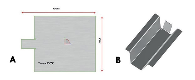
Fig. 1: A) Dimension of the sheet metal used. B) Geometry of the final product.

Table 1 – Input parameters in the simulation of the hot forming process.
Hot forming parameters
Complete austenitization of the material and fast cooling are prerequisites for achieving complete martensitic transformation during the hot forming process. According to the steel phase diagram, the austenitization takes place at temperatures around 900°C [6]. To avoid bainitic transformation, the cooling rate should be at least 27°C/s, so that the final microstructure is completely martensitic [7, 8]. The input parameters in the process simulation are shown in Table 1 and the considered punch and die face are shown in Figure 2.
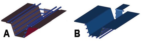
Fig. 2: A) Punch. B) Die face considered in the simulation.
RESULTS AND DISCUSSION
The simulation results evaluated in this study were: wrinkling in the part, thinning, post quenching mechanical strength, martensite content, hardness in Vickers, springback and temperature distribution as a function of cycle time, all as presented below.
Wrinkling & thinning:
According to the input parameters, material used and tool kinematics, the part presented no risk of wrinkling, as shown in Figure 3A. Thinning of the part thickness was in the order of 1.3% for the blue central region and 6.1% in the region near the edge, while no thickness reduction was observed in any of the other regions. Figure 3B illustrates the thinning of the part.
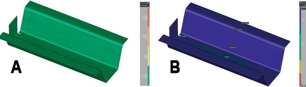
Fig. 3: A) Result regarding the risk of wrinkling. B) Thinning given in percentage.
Mechanical tensile strength & martensitic transformation:
After the hot forming process, the material achieved a high tensile strength, particularly in comparison with the base material, which has a mechanical tensile strength of almost 500 MPa, as indicated in the catalog. After the hot forming process, the resistance was approximately 1,430 MPa on the sides of the part and up to 1,490 MPa in the middle of the part, as shown in Figure 4A.
As a result, the simulated hot forming process proved to be successful, given that the martensitic transformation achieved 100% in all areas of the part, as shown in Figure 4B.
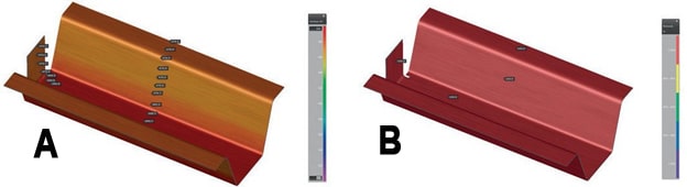
Fig. 4:A) Part tensile strength after forming. B) Percentage of martensitic transformation after conformation.
Vickers hardness & springback:
Both hardness and tensile strength also yielded a significant increase, remaining between 470 and 490 HV along the part, whereby this value increased from the lateral sides towards the center, according to Figure 5A. The springback of the part after the forming process was basically zero in the central and lateral sections of the part, with a 0.5 mm module in the flaps. Figure 5B shows the springback of the part.
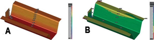
Fig. 5: A) Vickers hardness after forming. B) Springback generated in the part after forming.
Temperature distribution depending on the cycle time:
Lastly, the final temperature of the piece after the hot stamping process is illustrated in Figure 6A. At the output of the process, it was observed that the part contained sections with temperatures of 132°C. As with sheet handling at the tool entrance, the process required the use of relevant safety equipment. For study purposes, a condition was evaluated that increased the cycle time of the process in order to reduce the part temperature at the exit of the tool. With a cycle of 45 seconds, we obtained a product with maximal temperatures of 49°C. Figure 6B shows the temperature distribution over the entire part. However, the high cycle time does not compensate the achieved cooling in industrial terms.
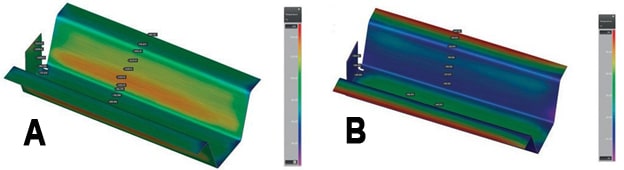
Fig. 6: A) Output temperature after forming, taking into account a total cycle of 22 seconds. B) Output temperature after forming, taking into account a total cycle of 45 seconds.
The final temperature of the tool during the 22-second cycle revealed that the punch and die face finished the first cycle at low temperatures, with greater heating at the ends, as shown in Figure 7.
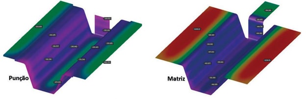
Fig. 7: Final temperature at punch and die face after the first cycle.
CONCLUSIONS
From the present study, we can conclude that both the simulated tool and the input parameters used for the USIBOR1500 material in the hot forming process were suitable, resulting in a part with extremely low springback and thinning and with 100% martensitic transformation. The end result is a high strength part with values close to 1,500 MPa in thin sheets, representing a process with great potential for customers in the automotive industry.
About the author:
Ibson Ivan Härter – ibson@bruning.com.br – Mechanical Engineer, Master’s degree student at UFRGS/DEMEC. Ibson is responsible for simulations of stamped parts and structural simulations, where he works as a Tool Simulation Specialist at Bruning Tecnometal Ltda., Panambi/RS, Brazil.


?")


