
Trimline optimization serves as the third pillar of the tool tryout process, alongside springback compensation and tool spotting. Its objective is to produce a part that adheres to specified profile tolerances—a challenge facing many tool construction companies prior to tool buy-off. (For additional information on AutoForm solutions for the first and second pillars, refer here and here.)
Italian toolmaker Gallarati s.r.l., headquartered in Pontida, Bergamo, is well-versed in the intricacies of trim optimization. The company boasts a tool engineering department, a toolshop, and a part production department. We invited them to share their expertise on achieving this critical objective.
Figure 1 – Gallarati s.r.l. logo
Firstly, when it comes to optimizing trimlines, the traditional approach often involves a manual trial-and-error method, comprising the following steps :
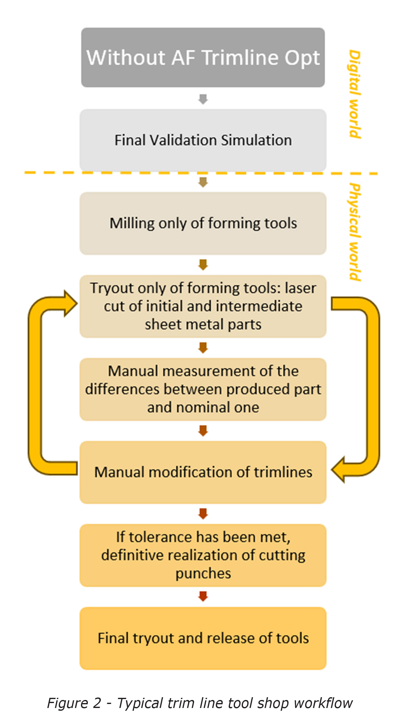
- Conduct a Final Validation Simulation using manually calculated developed trimlines.
- Mill only the forming tools and assemble the forming operations in the process line. Since the trimline is not yet finalized, cutting punches cannot be milled or cut using EDM at this stage.
- Perform tryouts solely for forming operations. Sheet metal cutting at the beginning and between operations is executed with laser cutting. Occasionally, this may require transporting sheets or semi-finished parts to another workshop for cutting, thereby increasing both costs and lead time.
- Manually measure the discrepancies between the profiles of the final part obtained from the tryout and the nominal specifications.
- Modify the trimlines and loop back to step #3 until the discrepancies fall within predefined tolerance.
- Once the final part from step #4 meets the profile tolerances, the cutting punches are milled or cut. Only then can the tryout of the entire process line proceed, followed by the final release of the tools.
The time span to complete such a cycle can extend to several weeks. Moreover, the manual nature of this procedure can exacerbate error propagation, potentially widening the discrepancies rather than narrowing them to meet the required tolerances. For instance, consider the challenges involved in accurately positioning a semi-finished, laser-cut part during an intermediate operation of a progressive die.
In contrast, using AutoForm’s Trimline Optimization allows for a digital execution of the cycle between steps #3 to #5 from the previous list. The revised workflow is as follows:
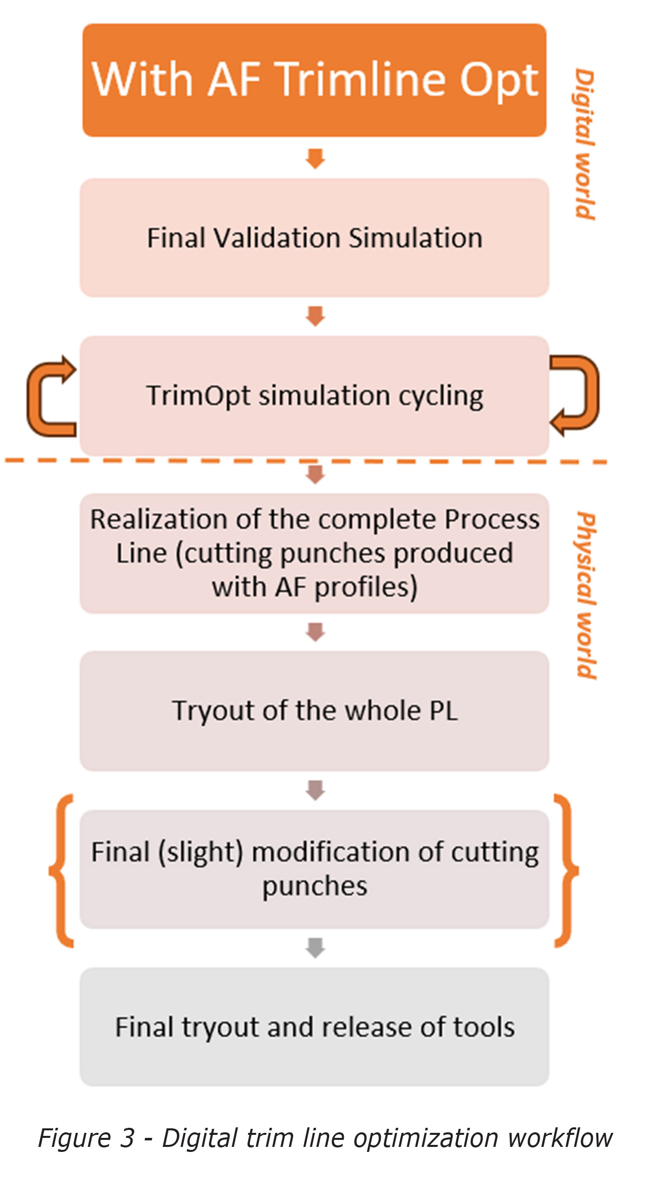 Conduct a final validation simulation using manually calculated developed trimlines.
- Engage in a cycle of trimline optimization simulations.
- Mill the complete set of tools and assemble the entire process line. The cutting punches are produced using the digitally optimized trimline generated by AutoForm.
- Conduct a tryout of the entire process line and verify the final part’s adherence to profile tolerances.
- If necessary, make final modifications to the cutting punches to meet profile tolerance requirements.
- Perform the final tryout and release the tools for production.
This approach significantly reduces lead time, eliminating weeks spent on trials and cutting down on transport costs to and from the laser cutting facility.
When using AutoForm for digital optimization, there are two possible outcomes: either the edge line of the part converges toward the required tolerance or it does not.
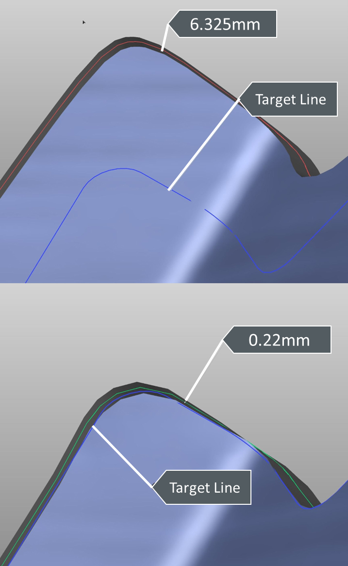
Figure 4 – Before (top) and after (bottom) the trimline optimization process in AutoForm
Fig.4: the blue line in both pictures, represents the target line; in other words the edge line of CAD-0 part design. The red line in the top picture shows the edge line from the initial simulation, before optimization. The line is red-colored to highlight the non-compliance of its position with established tolerance (6.235mm from the target). In the picture at the bottom instead, the result of the virtual optimization loop shows the edge line colored green as it is within acceptable tolerance (0.22mm).
Let’s examine both scenarios in comparison to traditional methods.
Convergence Scenario
In our example, the starting point features an offset of 6mm between the predicted edge line of the part and the target (refer to Figure 3).
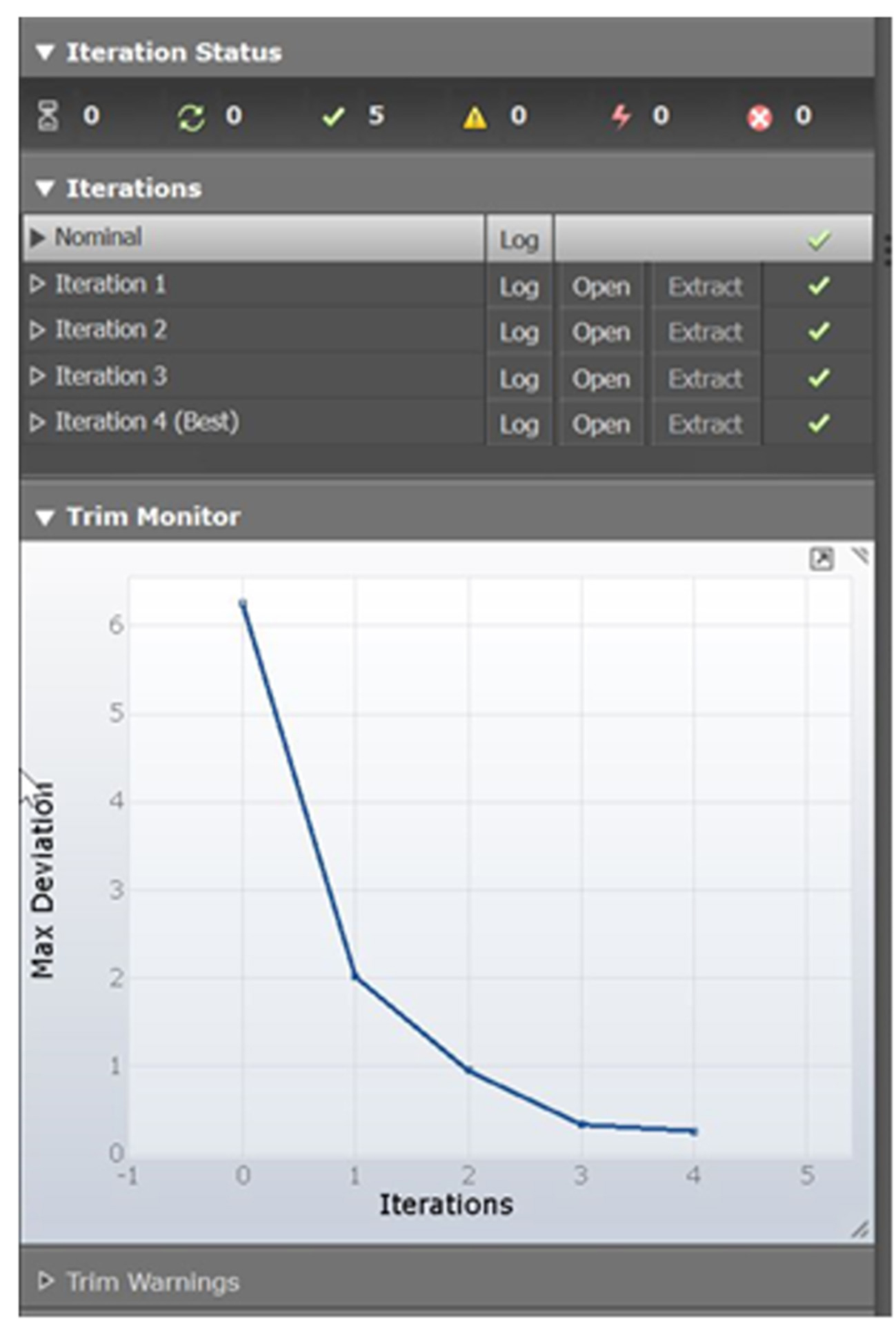
Figure 5 – Convergence behavior of the trim line
Without trimline optimization, four loops are required (as shown in Figure 5) to bring the edge line of the part within a ±0.3 mm tolerance. However, with digital trimline optimization, you eliminate the need for these four real-world loops, such as adjustments to the laser-cutting machine. The only requirement is additional calculation time, making the time and cost savings substantial.
Non Convergence Scenario
As illustrated in Figure 6, if the results after three loops fall short of meeting the requirements, further adjustments to the trimline become necessary. Unfortunately, any adjustments beyond this point tend to worsen the outcome. In a real-world setting, this could lead to a considerable expenditure of time and resources as you fruitlessly search for a convergence that is unattainable. Additional trimline modifications would likely impact other process parameters, leading to results that are counterproductive.
However, by conducting this analysis digitally, a modest increase in calculation time allows you to determine that the best possible outcome has already been achieved after three loops. This insight eliminates the wasteful expenditure of time and resources in chasing an unattainable solution under the current process setup.
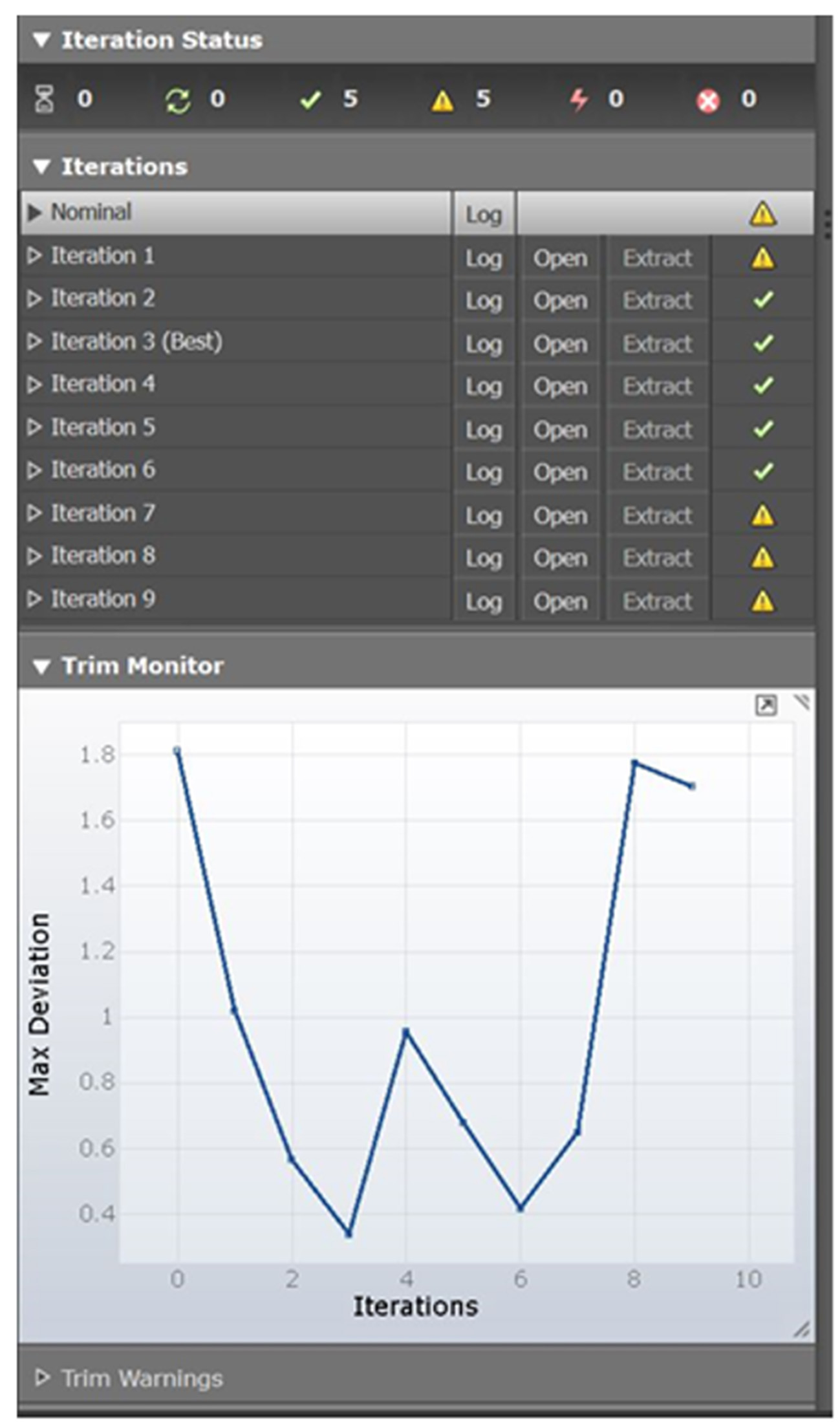
Figure 6 – Non convergence behavior of the trim line
In summary, any adjustments made after the tools have been produced can result in increased costs and time. Trimline Optimization is one of the valuable features that AutoForm offers, allowing users to shift these modifications to a virtual environment where the impact is significantly reduced.
We extend our thanks to Gallarati for sharing their insights and experience with us!


?")


