
Adapt, Improvise, Overcome: Facing the Challenge of New Materials
The Forming Analysis Team at Volvo Cars internal tool room has been using forming analysis solutions for twenty years. With Volvo’s XC40 model currently advancing to “all electric” its lightweighting development required the use of high strength steels. To handle a big scoop of parts in such materials was new to the Tool & Die facility in Olofström. In this post, Fredrik Håkansson, Project Manager T&D, shares their results.
In 2018 Volvo announced its famous XC40 model would be now transformed into the XC40 Recharge, an all-electrically driven vehicle, the first ever 100% electric vehicle from Volvo, in fact. Contrasted to their hybrid model, greater demands on lightweighting naturally arose, with engineers needing to consider the use of stronger materials, especially where safety is concerned. Stronger structural parts utilizing high strength steels were designed, especially seeing with electrification the combustion engine has been removed this demands OEMs completely rethink a vehicle’s front structure and safety components.
Volvo’s video discusses the new structural issues:
Volvo Cars decided that their internal supplier, Volvo Tool & Die in Olofström, Sweden, would produce several of the XC40’s new parts, including AHSS formed parts. However, this was a new challenge. High strength steels are famously known for its difficulty in achieving springback compensation within tight tolerances. Their internal tool shop normally produced hoods, fenders, doors and tailgates as their basic scope of products. Their assignment to produce such parts, however, meant that new skills would have to be integrated into their organization to meet the challenge.
“We were given the responsibility to produce Side members, A-pillars, Sill structures, Floor parts and other structure parts. Some of the A-pillar parts that were previously hotformed would now be AHSS panels instead. Normally we have maybe one part per project in such material. This big scoop of parts in high strength steel materials were new for our tool shop. Because of this, we wanted to develop a new workflow when it comes to simulation, especially for achieving springback compensation, digitally and in tryout.”
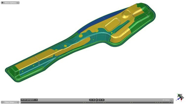
Fig. 1: Draw die for Rear sidemember compensated in AutoForm Compensator
Some of these parts experienced extreme springback, ranging from 15mm to 25mm in simulation, which demanded a serious compensation strategy be introduced to their facility. For example, the sill-inner, made from DP800, experienced sidewall curling and twisting. Therefore, aside from handling new materials, the team would now have to learn new skills. AutoForm-Compensator was introduced to the team. Utilizing this solution Volvo Tool & Die took a broad approach, covering five structural parts all at once, including the two A-pillars, the sills, and two side members, which are all known to present challenging springback issues.
Fredrik Håkansson reported that:
“Our team has a lot of simulation experience, some having used AutoForm for twenty years. One of our engineers quickly mastered the method and mentored others at CAE-department to spread the knowledge. Besides, the collaborations with AutoForm was supportive. Our team commenced early feasibility studies, which once confirmed, saw the compensations run in the next phase to handle the springback observed in our previous simulations. Furthermore, the scan data of the physical part was imported into the generic compensator to bring the part closer to tolerance. This has become our new workflow.”
“The tryout team focused a lot on spotting, which is always important, but in this case they paid even more attention to it. One factor to the success was that an early test of the tools was carried out early in the production to ensure that the result was the same as the tryout press. This extended our engineering efforts beyond tryout and all the issues were correctly predicted in digital engineering. The big difference is that previously, in dealing with parts like hood outers and inners, which was normal for our tool shop, we could decide on compensating the hood inner only, for example, and thereby wouldn’t need to compensate the outer seeing the inner structure would pull it into shape. With the introduction of structural parts, we were forced to compensate everything in its entirety during the engineering phase. Our target then was to compensate everything within +/-0.5mm.”
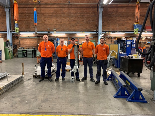
Fig. 2: Project Manager Fredrik Håkansson and the Tryout Team at Tool&Die
“One of the other things we had not done before is compensating all the remaining dies, by including digital draw-shell compensation studies, which included trim dies as well, so that each die saw its own unique compensation strategy implemented. In this respect, the simulations were quite complex and the studies thorough, as part of the new workflow. The shift to AHSS meant a greater focus on digital engineering. The use of compensation and its application on all the remaining dies for the part forming was an entirely new strategy.”
“Admittedly, there was skepticism on our side regarding the accuracy of AutoForm’s compensation solution. But because these were new and difficult parts we were willing to try. It’s not until you have all the facts on the table and the resulting parts have been measured that you can evaluate the software. So, faced with something you’ve never done before there is a sense of uncertainty. But, our tryout team had to make some tough decisions at the start of the milling phase. That was the moment when we had to trust that the compensation in the software was correct and take the leap of faith. At the end of the trial and project we recognised the new solution enabled our team to achieve success. Therefore, we finalized the tools much faster than expected, despite the tough material. In the finish it required just one quality loop to achieve tools could be delivered to the press shop.”
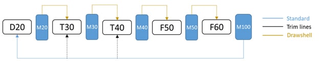
Fig. 3: Compensation strategy for the simulation.
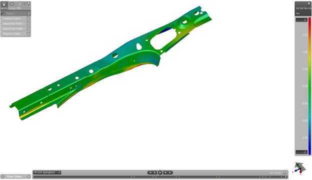
Fig. 4: Good springback result achieved by using AutoForm-Compensator.
“I have to credit the generic compensation functionality, which, although is quite a simple feature in AutoForm, was extremely helpful for the quality loop. One of the key factors to our success was that we could import the scan data and generate a vector field between the nominal data and the outcome from the first tryout. This vector field can be utilized for a second compensation study, which allows you to quickly get even closer to the target. That’s why we succeeded in just one quality loop. The first tryout result was based on AutoForm Compensator and the quality loop was successful thanks to the generic compensator tool.”
“The value to the organisation is that the effort was not wasted in tryout. For the team it meant a longer engineering study than normal as the compensation of panels in AHSS was a new experience for the whole organization. Therefore, achieving results that can be engineered in reality is obviously going to benefit our team for handling other materials and other panels in the future as well.”
Congratulations to the nine members of the Olofström simulation team at Volvo Cars. New readers, don’t forget to sign up to our blog.


?")


