
Two Simple Strategies You Can Apply in AutoForm to Improve Oil Canning on Sheet Surfaces
In this blog post Curtis Hsiung, Application Engineer from AutoForm USA, reveals how to handle the excess bulging or buckling of a sheet metal surface, better known as the problematic “Oil Canning” effect. While sheet metal stamping experts can evaluate and improve result variables, the phenomenon of oil canning is not as easily quantifiable. Curtis offers two strategies to effectively remove the bulging material and minimize springback. This is part 2 of our Oil Canning Series, where part 1 dealt with methods of identifying this problem.
Oil-canning usually occurs when sheet metal accumulates compression during forming; this compression may occur either over surfaces that lack geometric rigidity, or may be surrounded by surfaces lacking rigidity of stretch. When the panel is removed from the forming tool, accumulated compression causes sheet metal to stretch, and buckle if resisted. This buckling may happen in one direction or another; once formed, such buckles can be reversed with relatively small force – therefore the term “oil canning”.
The issue of oil-canning needs to be identified and addressed because it jeopardizes the robustness of the produced part, which in turn can affect the process of springback compensation inside and how accurately the simulated conditions predict real die conditions.
The example part below has substantial thickening and compression issues in the flat area. Its nominal part shape and the simulated sheet after springback are displayed below with different result variable views.
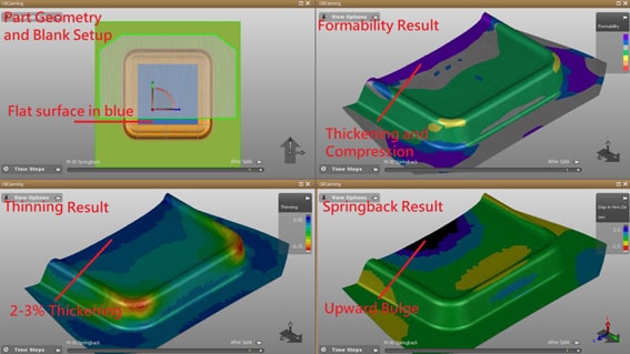
Fig. 1: Part and Finished Sheet. In AutoForm the colors imply: purple=thinning, yellow/orange= a lot of stretch for formability, blue=thickness increase, orange/red=thickness decreases. Red risks of splits. Dark purple=thickening. On the Formabilty check, grey=not enough stretch.
From the springback results in the lower-right tab in Figure 1 above, we can see how the sheet bulges in convex direction. In order to geometrically compensate such springback, the surfaces would be morphed in reverse from the springback direction. However, due to the fact that the convex shape shown in the springback tab in the figure is geometrically weak, the attempt at compensation only causes the convex shape to pop into a concave direction. Subsequent springback compensation attempts cannot converge as shown in the figure below. No matter how many compensation iterations are attempted, the stress conditions will still cause the surface to bulge up or down.
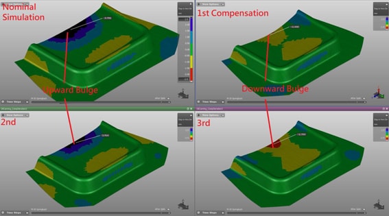
Fig. 2: Compensation Attempts
In short, an oil-canning issue will not allow springback compensation methods to converge. In order to avoid this problem we must first know how to identify where oil canning is occurring on a metal surface (see Oil Canning Part 1: Identifying Oil Canning) and secondly we must have strategies to deal with it.
One of the ways to strain the sheet is by adjusting appropriate process parameters such as bead strengths, binder tonnage, binder stroke, etc… Adjusting these process parameters can potentially restrict material flow into the area thereby changing the strain magnitude and direction to a more beneficial condition. Another way to help reduce oil canning is to add a geometrical feature to the part design or addendum design. The scope of the additional geometric feature is to increase section inertia and consequently neutralize the buckling effect.
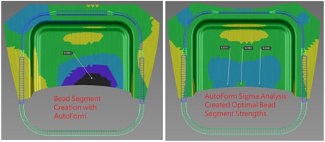
Fig 3. Springback after Bead Strength Adjustment and Analysis
Shown above in Figure 3 are the original simulation on the left and a modified simulation on the right. The beads on the right image have been adjusted to produce more tension across the region of concern, while there is a decrease of the straining force on the top to allow more material flow. As shown, this has an improved effect on the springback amount, and we would hope this also trends towards less sensitivity to oil canning. (To see how other features of AutoForm allow for a quick analysis and implementation of these types of process adjustments, please read: Systematic Drawbead Design for Optimal Process Definition).
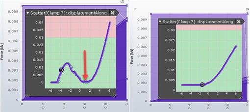
Figure 4. Clamp Force Plots for the Evaluation of Oil Canning. X axis is the displacement along the normal line (movement of the sheet), and Y axis is the force in kN.
Using the method as described in Part 1 of this series, which is to set up a clamp where its location is variable within a certain distance range in the normal direction to the flat surface of the part geometry. With x-axis as the clamp location in the normal direction of the oil-canning flat surface and y-axis as the reaction force exerted on the clamp by the sheet, we can see in the plot on the left in figure. 4 that the force increases until it pops the springback in the opposite direction from the initial springback direction, dropping the clamp force to zero since the clamp loses contact with the sprung panel. The improved process of optimizing bead strength is able to eliminate the indication of oil canning in the identification method. However, this is still no guarantee that compensation will be successful, but it is an improvement.
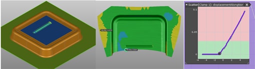
Fig 5. Adding Geometric Feature and Its Oil Canning Improvement Effectiveness
The second countermeasure for Oil Canning is to add some geometrical shape. The purpose is to provide a shape which has sufficient strength to resist the buckling. One idea would be to add a metal gainer or “bead” or emboss shape to the geometry of the part. It may also be possible to add the shape to the addendum in order to improve the sheet behavior between specific operations even if it is in a scrap area. Shown above in Figure 5, a straight bead has been added to the part geometry in the region where the bucking was observed. Of course, this may not always be a possibility due to part design. However, it may be possible when all other countermeasures have been exhausted. The emboss shape provided more geometric rigidity and its springback result shows a decrease of springback magnitude. Using the same method as in Part #1 again, we find that the force drop is no longer observed.
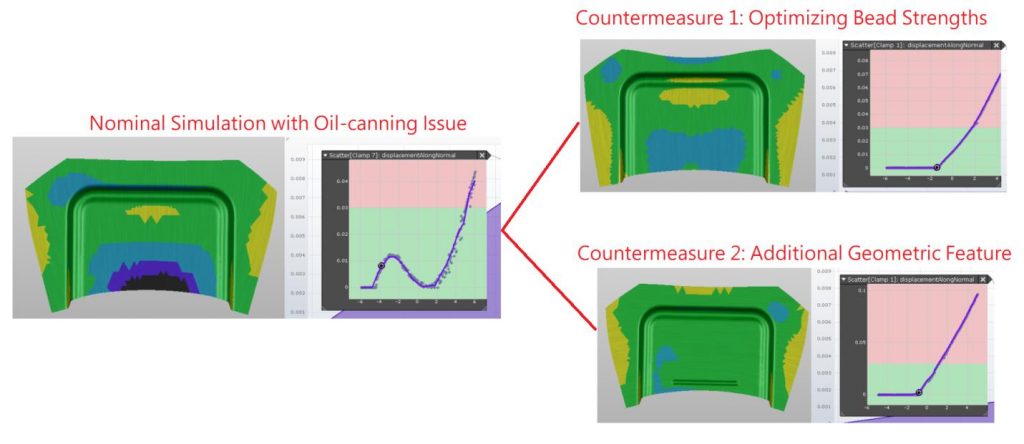
Fig. 6: Springback and Oil Canning Improvement after Countermeasures.
Compiling the original springback and oil canning identification condition with these after-countermeasure results in figure 6, we can see that such countermeasures not only improve the springback magnitude but also eliminate the oil canning condition. The application of these two countermeasures will prove valuable to users who encounter oil canning conditions.
For training on identifying and handling this issue yourself, contact your local AutoForm Office.


?")


