
This is part 2 this series. You can see part one here, which explored the importance of material characterization in stamping processes. Now, Joao continues to explore the characterization of sheet formability limits.
Tensile test with lateral restriction
The tensile test with lateral restriction (Figure 10) can be used to generate a plane deformation state on the material being studied. By changing the radius size r of the test coupon as illustrated in Figure 11, it is possible to enable some lateral narrowing degree of the coupon. This makes it possible to cover part of the compression region of the FLD, as well as the plane deformation region. The procedure was developed in 1972 by Rozzo and Deluca [5].
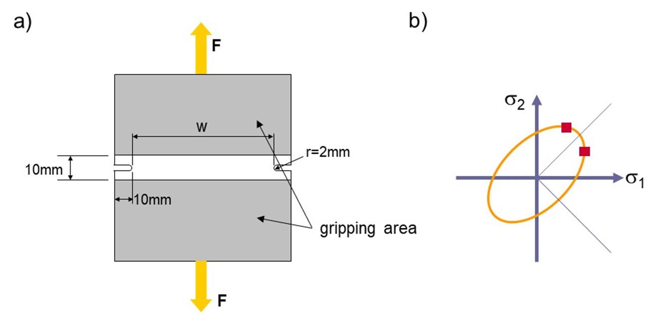
Figure 10: a) Test coupon geometry; b) Flow envelope locations that are determined in a planar deformation state. Source: [1].
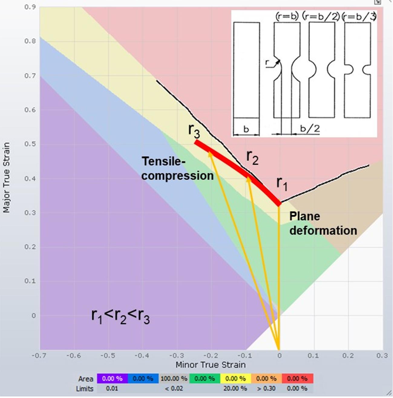
Figure 11: Method developed by Rozzo and Deluca [5] for determining the FLD left side. Source: [1].
Tensile-compression test
Also referred to as wedge testing according to Sachs [6] (Keilzug-Pruefverfahren nach Sachs, in German), the tensile-compression test is characterized by the application of uniaxial tension overlapped by compressive stresses generated by lateral wedges. Deformations can be analyzed by methods such as visioplasticity.
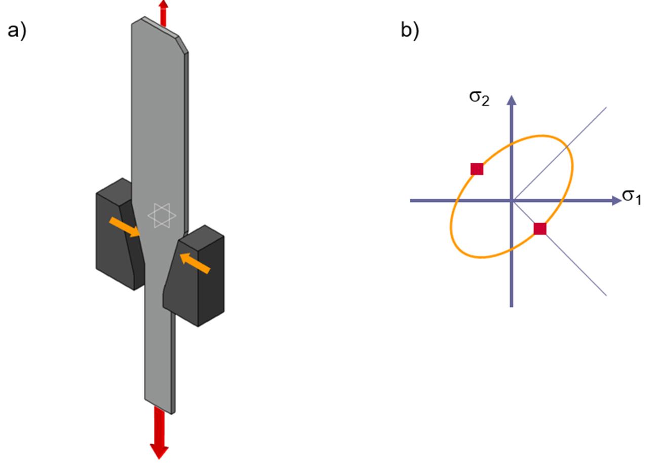
Figure 12: a) Representation of the wedge-shaped coupon while testing. b) Points on the flow envelope represented by the test. Source: [1].
The test reproduces the stress-compression state present in flange regions of the deep drawing process. A disadvantage of the test is that the generated friction in the contact regions of the wedges has a great influence on the result and is thus very sensitive to lubrication conditions. In the flow envelope the points represented by the test are in the shear regions (Figure 12-b).
Stacked compression test
Pawelski [7] was the first to conduct a compression test with stacked sheet metal specimens. The stacked compression test is an adaptation of the cylindrical compression test according to DIN 50106 [8]. The advantage of the compression test compared to the tensile test is the greater degree of deformation that can be achieved, since the material cannot shrink under pressure. Due to the small thickness of the material, multiple individual specimens are stacked in the layer compression test, so the specimens must be aligned uniformly with respect to their rolling direction. For reducing the friction effects, Teflon sheets are used at the interfaces between the compression bands and the coupon. Deformations that occur in the circumferential direction are logged by the optical deformation measurement system. The yield stress is determined by the detected deformation forces and the cross-sectional area of the specimen, which is considered ideally cylindrical. The compressive stress in the direction of the sheet thickness leads to a uniform expansion of the specimen (Figure 13). The length increases in the x and y directions are dependent on the normal anisotropy.
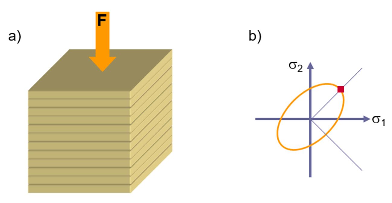
Figure 13: a) Representation of sheet specimens stacked for testing. b) Point on the flow envelope represented by the characteristic test of a plane stress state. Source: [1].
Shear test
Shear tests after Brosius [9] are employed to test sheet metal materials under simple optimal shear. This test allows the flow resistance under shear stress to be measured. The tensile force and the length variation are registered by the jaws of the testing machine (Figure 14). The shear stress is determined through visioplasticity deformation analysis.
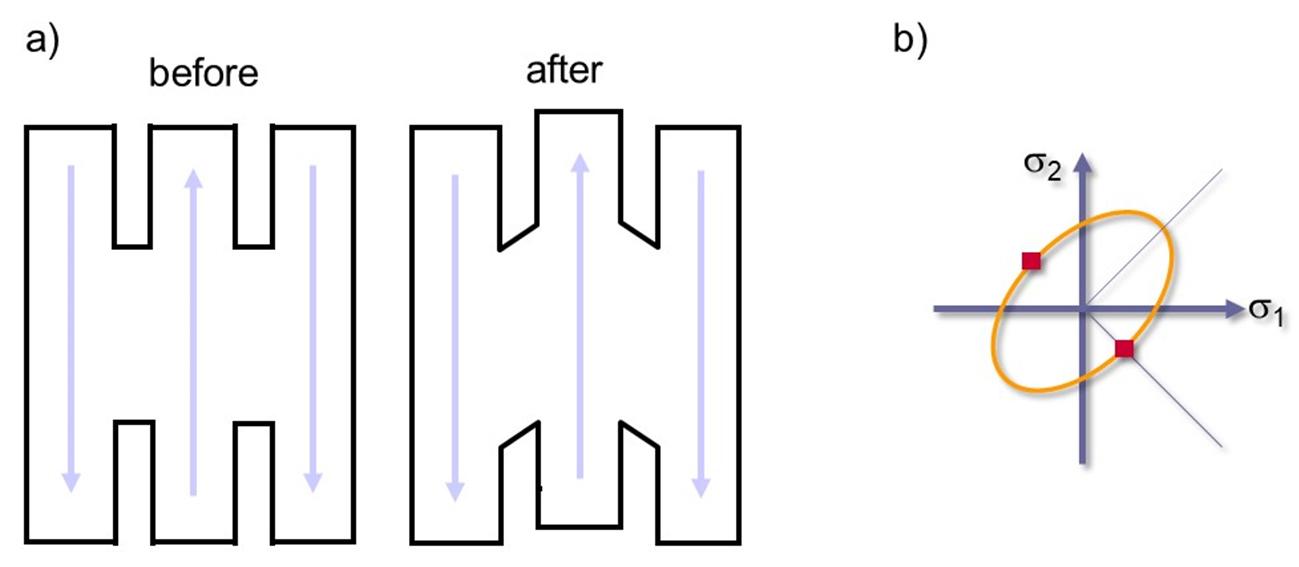
Figure 14: a) Coupon before and after testing) Points on the flow envelope, characteristic of shear. Source: [1].
Bulge test
The hydraulic expansion test was introduced by Hill [10] (1950) and is frequently used for the determination of yield curves up to true deformation degrees of about 0.7. The Figure 15 shows the principle of the process where a fluid is pressed from one side into a rigidly clamped round specimen. By means of the medium pressure, the specimen expands and finally ruptures at the cap pole. Fluids (generally oil or water based media), gases, and viscoplastic media can be used. The media pressure is measured by means of a pressure sensor and the sheet radius and thickness at the specimen pole is measured optically or with a tactile method (Figure 16).
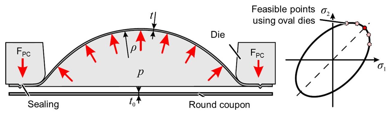
Figure 15: Principle and reachable stress states of the Bulge hydraulic expansion test. Source: [1].
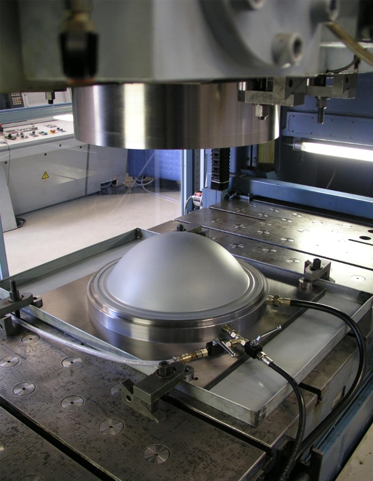
Figure 16: Photo of an assembled bulge expansion test (source: IFU Stuttgart).
Nakajima and Marciniak tests
As mentioned earlier, the standard for the evaluation of the Forming Limit Diagram (FLD) is ISO 12004 [2, 3], which describes the test procedure as well as the evaluation method. The development of the standard has attempted to keep the definition of the FLD simplicity. In effect, despite the large number of test setups available for material characterizations, such as tensile test, Bulge test, plane deformation tests, the standard prescribes the use of only one elongation setup with two punch variants, namely a hemispherical punch according to Nakajima [11] and a flat punch according to Marciniak [12].
To find a universal definition of the forming limit diagram, Nakajima proposed a test setup for the analysis of multiple deformation conditions using a unique tool setup. The so-called Nakajima test consists of a clamping unit and a hemispherical punch. The different deformation configurations are obtained with multiple specimen geometries. The specimens are strips whose width changes according to the desired deformation history, which might vary from the biaxial condition with full geometry to uniaxial stress with small widths (Figure 17).
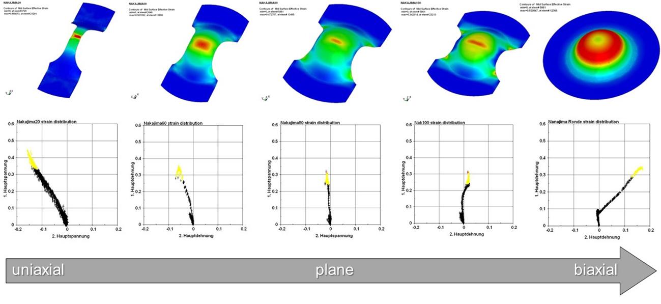
Figure 17: Influence of different coupons on the deformation path in the Nakajima test. Source: [1].
They also observed that the most severe deformation condition, in which the lowest FLC (Forming Limit Curve) point is reached, matches the plane deformation condition. Marciniak proposes a machine configuration similar to Nakajima’s test, but using a flat punch. Due to the critical contact condition between the sheet and the flat punch, the so-called Marciniak test requires a support plate between both contact surfaces. This ensures a homogeneous distribution of deformations (Figure 18). Both configurations are represented according to DIN EN ISO 12004-2 [3].
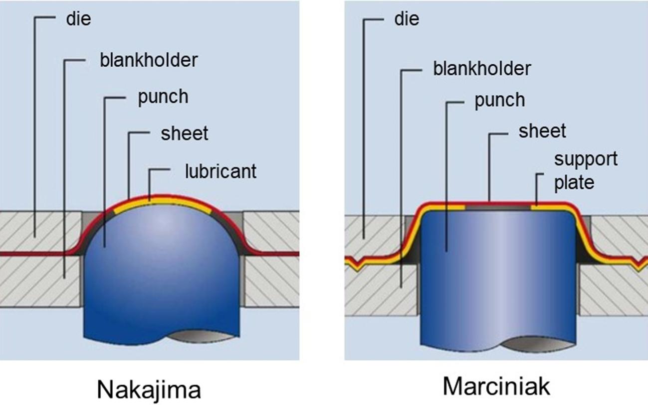
Figure 18: Differences between tool geometries according to Nakajima versus Marciniak. A support plate is used in the Marciniak test to allow the plane state deformations to develop in the flat region of the disk. Source: Erichsen.
Cross coupon tensile test (biaxial tensile)
A cross-shaped plate is tensioned in two axes in the biaxial tensile test, thus creating a multiaxial stress state in the central region of the test. The principle and the stress states that can be achieved are illustrated in the Figure 19.
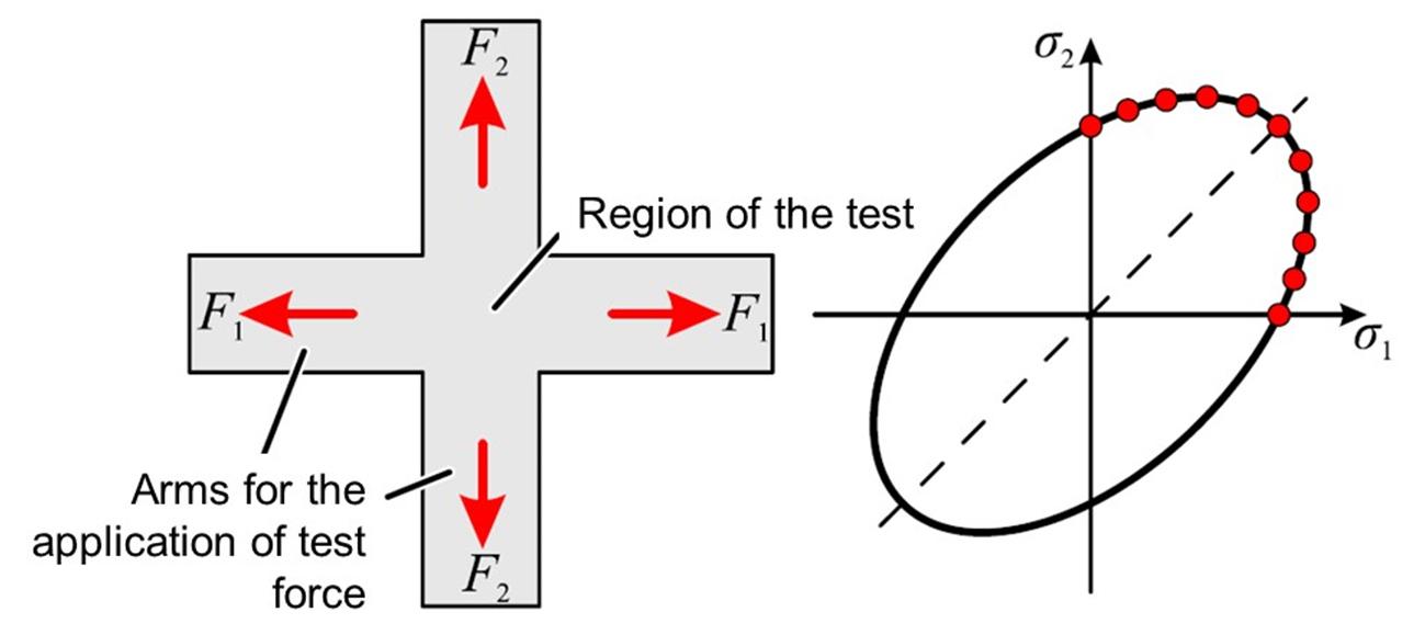
Figure 19: Principle and reachable stress states with the cross-shaped coupon. Source: [1].
In this test it is possible to vary the test force ratio in both loading directions. The flow start can be determined across the first quadrant of the flow envelope. The carrying out of this test is outlined in the standard ISO 16842 [13].
Without an additional modification of the coupon, even slight plastic deformation leads to coupon failure. To ensure the homogeneity of the stress state and deformation in the central region of the specimen, different coupon geometries have been developed, as shown in the Figure 20.
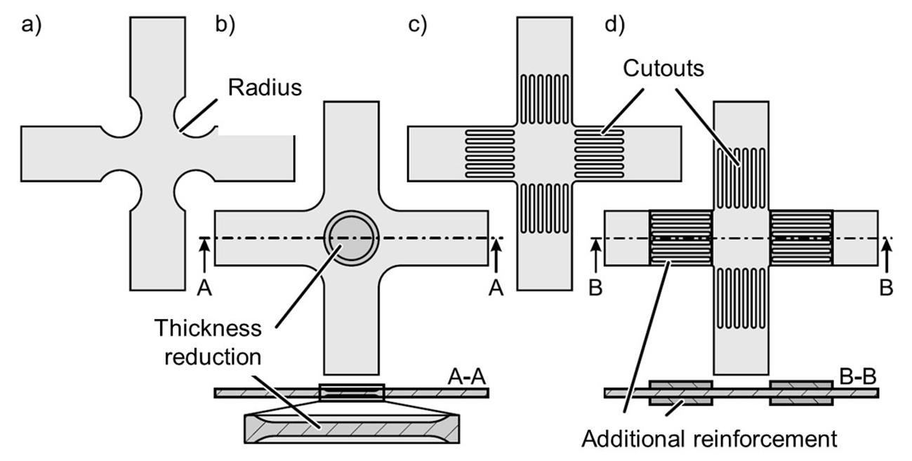
Figure 20: Biaxial tensile test adjustments with a) Radius variation (Shiratori and Ikegami, 1967), b) Sheet thickness reduction (Wilson and White, 1971), c) Cutouts in the arms (Mönch and Galster, 1963) and d) Additive reinforcement of the arms (Hou et al., 2021)
Bending test
The determination of the bendability of sheet metal is realized in order to determine the maximum achievable bending angle, e.g., by means of ISO 7438 [14]. Besides this, it is possible to evaluate the capability of a sheet to be bent and unbent in multiple cycles with the standard ISO 7799 [15]. It is worth mentioning that there are several non-standard tests, for instance for the determination of minimum bending radii.
Bending tests are useful to verify the material properties of materials utilized in the car body manufacturing (Figure 21). In hemming processes, the knowledge of the bendability and limits of the sheet is crucial.
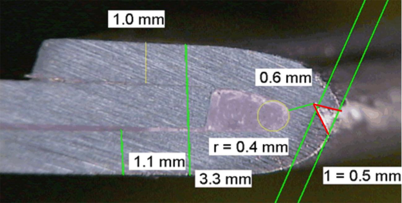
Figure 21: Cross-sectional view of a hemming joint in an automotive product that shows a failure in the outer region of the bend. Source: [16].
The standard EN ISO 7438 [14] describes an apparatus for the bend test with rollers and replaceable punch (Figure 21-a). The specimen is bent until a certain angle is reached or completely so that the bending capacity of the sheet is exhausted. The test allows the evaluation of a Bend Factor, obtained by the quotient between the internal radius of the bend and the thickness of the sheet, which represents the bendability of the material. This factor can be represented with respect to different degrees of stretching, since before the hemming step the component has been submitted to forming operations (Figure 21-b).
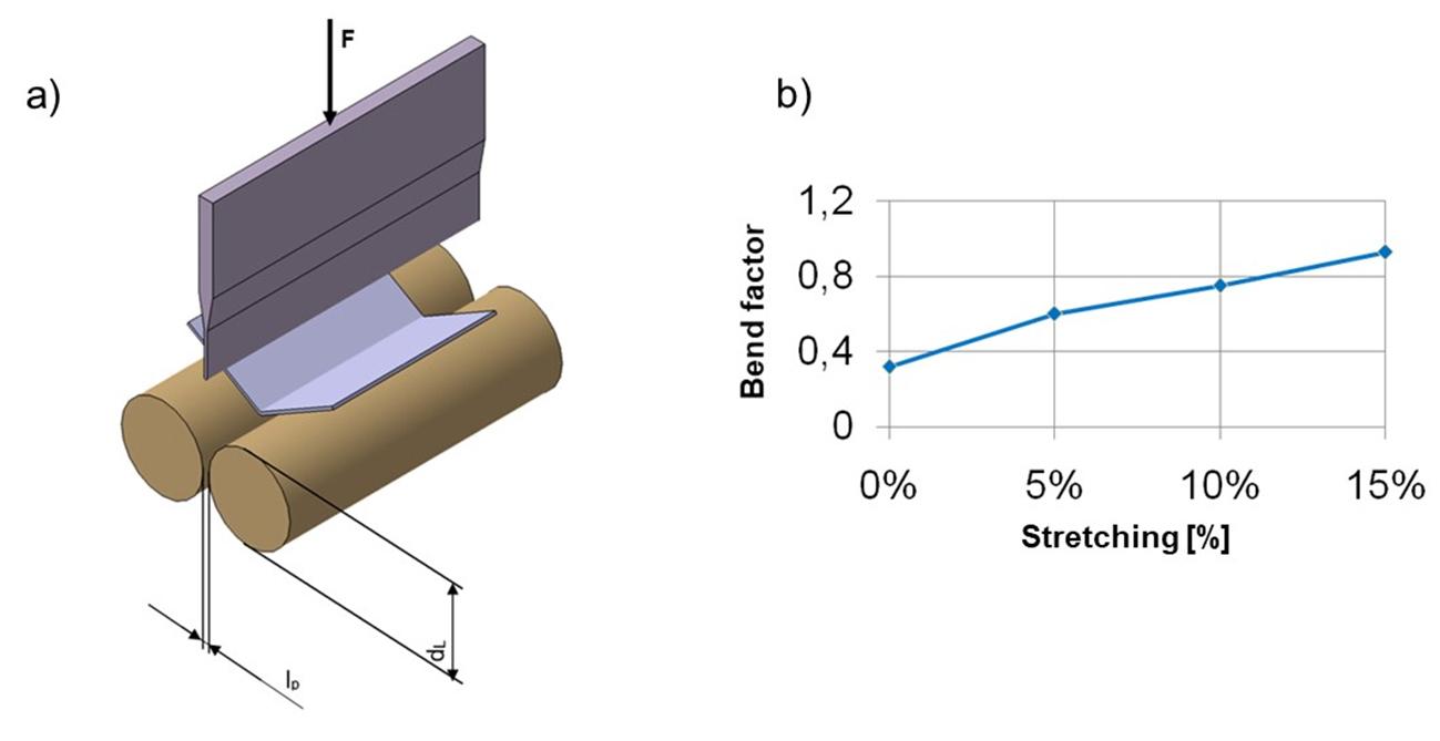
Figure 21: a) Bending device according to DIN EN ISO 7348.b) Stretching levels versus bend factor. Source: [1].
To complement this, after the test, the surface of the bended outer edge can be evaluated according to subjective evaluation criteria and defined in quality classes. A visual check takes place here, as no quantitative logging of the measured variables is possible. For multiple bending edge images, as seen in the Figure 22, degrees are provided and a failure limit is defined based on them. From now on, a grade of 2 to 3 is defined as the failure limit, which must not be exceeded in terms of quality.
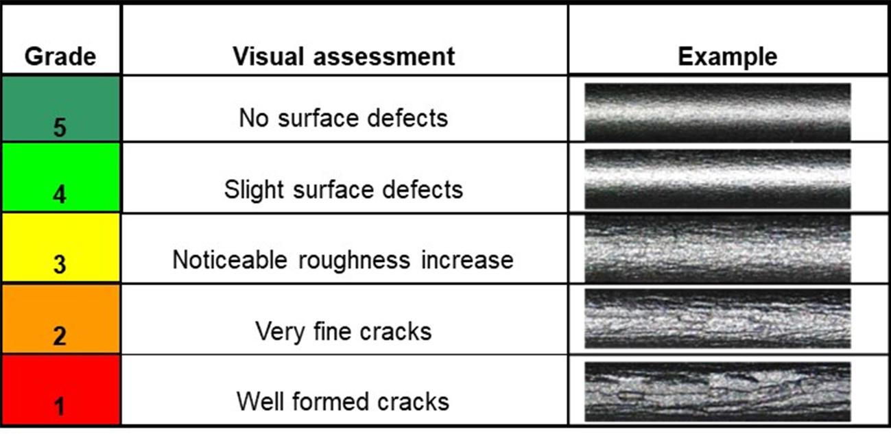
Figure 22: Quality grades for the bended edge surface quality. Source: [16].
Variability of mechanical properties
The sheets employed in the component manufacturing are subject to variations in their mechanical properties that originated in the coil production. The Figure 23 illustrates the variation of the anisotropy index in a cold re-rolled steel sheet within a unique coil. It is expected that all the other important properties for the process success will also vary, which certainly has consequences in the robustness of the process.
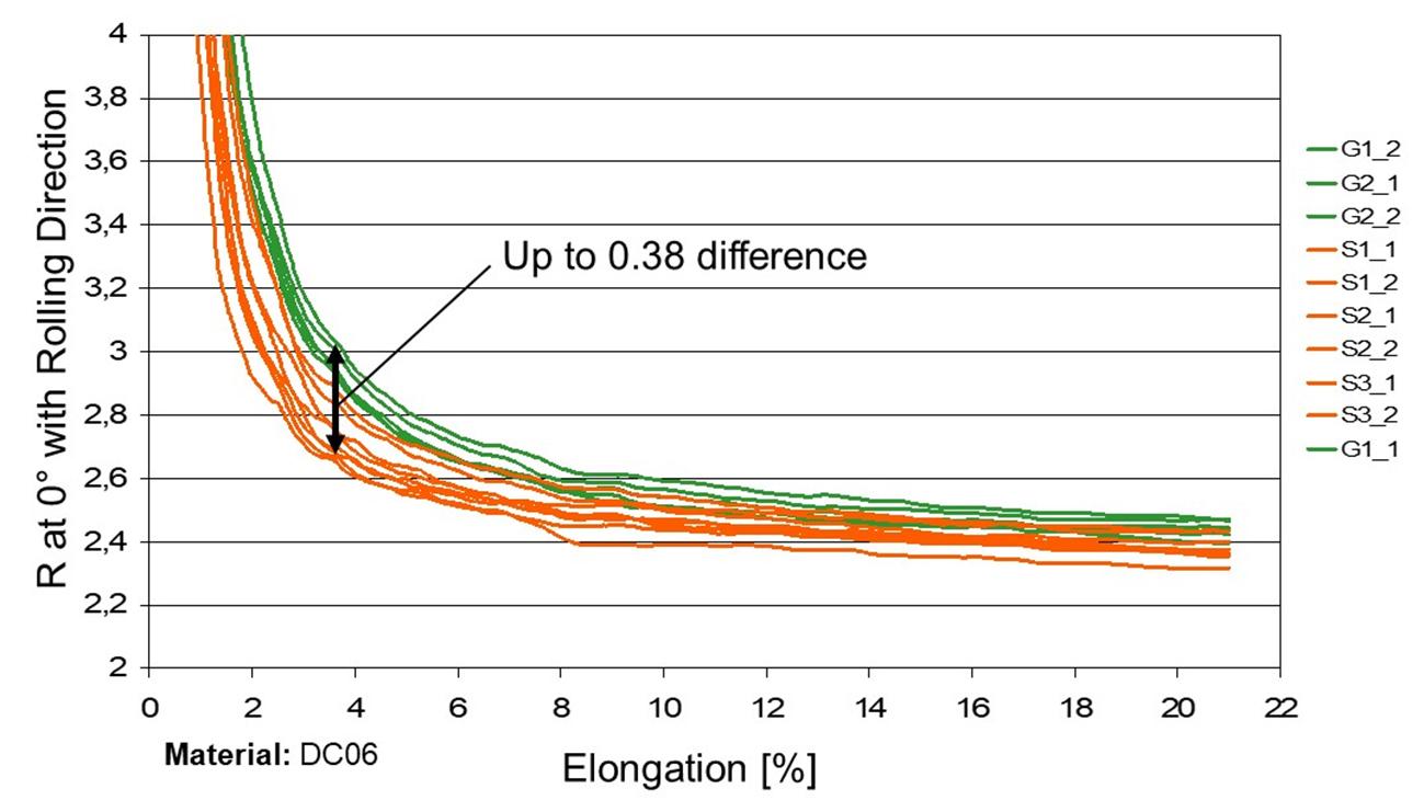
Figure 23: Variation of normal anisotropy in a DC06 sheet. Source: [1].
The use of singular simulation models can provide important information regarding the manufacturability of a component. However, since a single simulation cannot represent the natural variability of the parameters, the result does not guarantee a robust manufacturing process, as illustrated in the Figure 24.
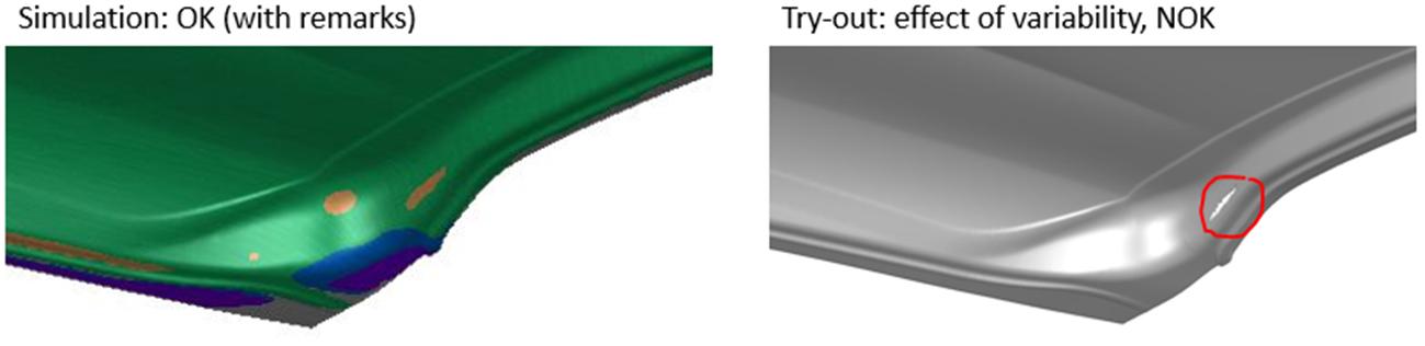
Figure 24: Result of singular simulation (right) carried out disregarding the variability of the material properties and the real part with a quality problem (left). Source: the Author.
The variations can be correlated not only to the mechanical properties, but also to process factors like blankholder force, tribology (friction), press speed, etc. These variations can be represented in the Finite Element Analysis (FEA), ensuring a process that will keep producing in a stable way even in a situation of unfavorable mechanical properties.
Conclusions
The correct representation of the plastic behavior of a material in all situations that occur in the industrial world constitutes a challenge that occupies researchers up to the present day. The different types of tests presented here have their own advantages and disadvantages, and should be applied according to how close or similar they are to the phenomena actually occurring in the process.
The measurement and mathematical representation of the variations that arise in mechanical properties is essential for conducting stochastic simulations. In a stochastic simulation model, it is possible to automatically scan the consequences of natural variations of the input parameters (including properties) on the simulation result. With the advent of Physics-Driven Digital Twins, the importance of the correct characterization of the materials increases even more. In addition, the capability to represent the variability of the real world is essential.
The future of engineering systems employed in stamping processes will require models that are accurate and at the same time have a certain “flexibility”, where information streams out of the system, gets compared with reality and re-enters the system. This enables the system to map the real world and its nuances and serve as a tool for scenario analysis and even autonomous process correction.

Dr.-Ing. João Henrique Corrêa de Souza worked as researcher from 2003 to 2008, earning a PhD degree at the Institute of Metal forming Technologies, Stuttgart University. In the industry, worked as a researcher, R&D Manager and Senior Engineering and Tool-shop Manager, from 2008 to 2020. Since 2020 is Visiting Professor at the Federal University of Rio Grande, Brazil. At the same time is the National secretary of the BrDDRG – Brazilian Deep Drawing Research Group and coordinator of annual the BrDDRG Sheet Metal Forming Congress and Owner and director of TechnNOVA Pesquisa Desenvolvimento e Inovação Ltda, as representative of Autoform Technologies in South Brazil and offering consulting/ training services in sheet metal forming and R&D.
https://www.linkedin.com/in/joaohcdesouzametalforming
References
[1] Liewald M. Vorlesungsskript Werkstoffkundliche Grundlagen der Blechumformung. 2009, Institut für Umformtechnik, Universität Stuttgart.
[2] ISO12004-1:2020 Metallic materials — Determination of forming-limit curves for sheet and strip — Part 1: Measurement and application of forming-limit diagrams in the press shop.
[3] ISO12004-2:2021 Metallic materials — Determination of forming-limit curves for sheet and strip — Part 2: Determination of forming-limit curves in the laboratory.
[4] ISO 6892-1:2019 Metallic materials — Tensile testing
[5] Rozzo B, Deluca P, Rendina R. A new method for the prediction of formability limits in metal sheets. 1972, Sheet Metal Forming and Formability: Proceedings of the 7th biennial Conference of the IDDRG – International Deep Drawing Research Group.
[6] Sachs G. Ein neues Prüfgerät für Tiefziehbleche. 1930, Metallwirtschaft 9, 213.
[7] Pawelski O. 1967 Archiv für das Eisenhüttenwesen 38 (6), 437-42.
[8] DIN 50106, 2016 – Testing of metallic materials – Compression test at room temperature.
[9] Brosius A, Yin Q, Güner A, Tekkaya AE. A New Shear Test for Sheet Metal Characterization. 2010, Steel Research International 82 (4), 323-328.
[10] Hill RC. A theory of the plastic bulging of a metal diaphragm by lateral pressure. 1950, Lond. Edinb. Dublin Philos. Mag. J. Sci., 41 (322), 1133-1142.
[11] Nakazima K, Kikuma T, Hasuka K. Study on the formability of steel sheets. 1968, Yamata Technical Report, vol. 264, pp.141-154.
[12] Marciniak Z, Kuczynski K. Limit strains in the processes of stretch-forming sheet metal. 1967, Int. J. of Mechanical Sciences 9 (9), 613-620.
[13] ISO 16842, 2021 – Metallic materials — Sheet and strip — Biaxial tensile testing method using a cruciform test piece.
[14] EN ISO 7438, 2020 – Metallic materials. Bend test.
[15] ISO 7799:2000 Metallic materials. Sheet and strip 3 mm thick or less. Reverse bend test.
[16] Heyvaert S. Überprüfung der Bördelfahigkeit. 2006, Gesellschäftspräsentation Corus Aliminium Duffel, Belgium.


?")


