
Every die engineer is familiar with the accompanying feeling of satisfaction when, after weeks of hard work, the tools start to move and produce high quality stamped parts. Unfortunately, that singular feeling of reward doesn’t last forever. Some stamping issues will soon snap you out of it. Why is this? How is it possible for a tool that was flawlessly turning out parts in the same quality range to suddenly start producing scrap?
There’s no mystery here. Every toolmaker knows that production conditions are, to some extent, out of their control. The real downside to this situation is that it can be extremely costly when a near-perfect tool begins randomly producing scrap.
In this article, I’ll share what happened when the die experts at Alastampi saw the quality of stamped parts drop below the acceptable limits with a previously reliable tool.
During initial feasibility, stamping engineer Mr. Luca Sacco defined and digitally validated the entire stamping process using AutoForm. He analyzed and corrected all possible forming issues for a 0.40mm stainless steel component. If you take a look at Figure 1, you’ll see that the process initially created parts meeting all necessary quality standard limits, for drawing and all subsequent operations.
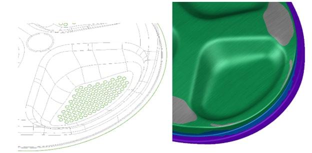
Fig. 1: Reference geometry and simulation results (formability)
After a few weeks, the first stamped parts were available for try-out. The quality control department gave the OK to begin pre-series production, as the tools were producing parts without any surface defects and within tolerance. However, during the preliminary production batch, some parts were rejected as scrap because they did not meet the quality standards: splits occurred in the embossment wall (see Fig. 2).
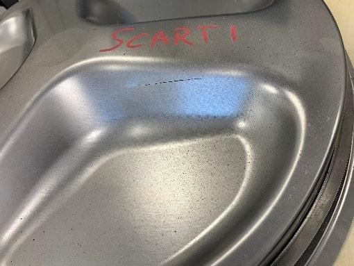
Fig. 2: Sample of pre-series production part with a visible split
With the scrap rate higher than the acceptable limits, sales manager Mr. Andrea Gagliardi asked the engineering team to investigate this issue and propose necessary modifications to reduce the scrap rate. After a few simulation loops, it was clear to the team that the issue did not arise from the tool or part surface, but from tribology and the rheology of the process (material flow and deformation).
To better understand the phenomenon, the team conducted a detailed sensitivity analysis of process parameters like friction and material properties. The analysis required the use of AutoForm Sigma, which allows designers to evaluate the influence of variable parameters on the final result. Only with complete process transparency can we get to the root cause of the problem. Since the split appeared to have occurred “randomly” during batch production and the part is axisymmetric, the idea was to set some variability in the following parameters:
- Material thickness
- Material mechanical properties (Yield stress, UTS, R values)
- Rolling angle
- Lubrication
What was the reason for selecting only these parameters? Mr. Sacco explained that they arrived at this conclusion by looking at both the part geometry and the split position. Since the part had a steep vertical wall and three big embossments at the center, the blank was circular, and the split appeared only in one single embossment at a time, the only possible culprit was material and friction properties. In addition, the circular blank made it impossible to guarantee the same roll-in orientation during positioning on the binder surface; this uncontrollable operation made the material flow and stretch differently with each press stroke.
Other process parameters like binder pressure and drawbead restraining force had a big influence on the external vertical walls of the part, as few simulation loops showed risk of splits, which never occurred in try-out. Thus, the decision was made to exclude those variables from the sensitivity analysis and instead focus on material and tribology systems.
Unfortunately, this first result wasn’t entirely satisfactory because, as Mr. Sacco reported to the AutoForm support team, the feasibility result showed good process capability (see Fig. 3), meaning the part thinning was extremely stable under those parameter variations. The simulation showed no signs of potential splitting, either in one or all three embossments.
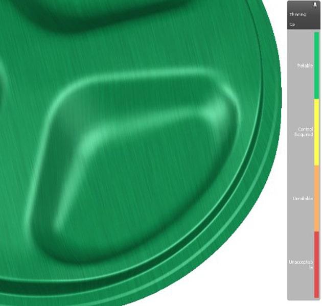
Fig. 3: First Process Capability Check on Thinning
The analysis at least showed that the material properties and friction had a direct influence on thinning, but offered no clarity about which parameter was the primary cause of the split.
Following an in-depth analysis of the case study, the AutoForm support team suggested basing the variability range of the material’s mechanical properties consistent with stainless-steel production variations, and introducing one of the advanced friction models available through AutoForm.
A new sensitivity analysis was set up and executed, with the friction coefficient varying with direction of stretch. As a result, the formability map came much closer to reality. The split was finally visible in one embossment wall for some specific combination of parameter values (see Fig. 4).
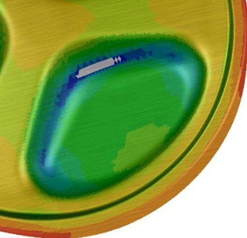
Fig. 4: The out of range thinning result shows the white area in a single embossment.
The process dominant variable results (see Fig. 5) showed a clear change in thinning influence on the embossment vertical wall, exactly were the split was occurring in reality. With this information, the team realized that when this parameter combination was replicated in real production, the part split and was therefore scrapped. Consequently, using this particular combination, the process was not robust.
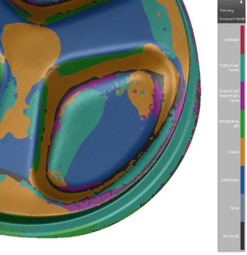
Fig. 5: Sigma dominant variable shows a clear change in parameters influence along the split area
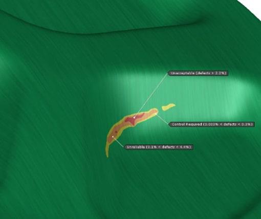
Fig. 6: Process capability issues identified within Sigma
The process capability results made it clear to Alastampi that it was impossible to increase the stability by simply adapting the few controllable process parameters in production.
The sensitivity analysis clarified the process limits and that it was necessary to request part geometry changes from the customer. As a result of the analysis, the request for the part change was related to the wall angle of the embossments. Only when this had been implemented could production proceed without unplanned press-line downtime, accompanied by a definitively lower scrap ratio.
Conclusion
It would have been possible to know in advance the root cause of the splitting and subsequent scrap rate by analyzing the variability of all the process parameter inputs. Running sensitivity analyses as the standard approach during production design is crucial to avoid unplanned and extensive try-out loops while maintaining lead-time.
I would like to thank Alastampi for allowing us to share another important experience.


?")


