
In our previous article, we covered how aerospace part supplier Senior Aerospace Thermal Engineering (SATE) a UK-based aerospace component manufacturer and part of Senior plc, an international manufacturer of high technology components and systems, integrated forming simulation software into their New Product Introduction (NPI) business. In this article, we explore a specific case encountered by SATE. This is part two of a three-part series.
Case 1: A Complex Part in Hot Forming
SATE had been approached by a tier-one supplier in Spain, who were interested in exploring the company’s potential approach to the manufacturing of component they had designed. While SATE had produced similar parts in the past, this one presented some unique challenges due to its double curvature design.

Fig. 1: Double curvature Ti pressing
Upon initial assessment, it quickly became apparent that a minimum of two parts would need to be produced by each forming cycle to make the process economically viable. This realisation uncovered the first challenge, forming the basis of the project’s tooling strategy.
Initial Attempt
Despite its seemingly straightforward appearance, the SATE team identified the part design as high-risk due to its double curvature design and the necessity to form two parts simultaneously with stringent thickness control requirements.
Initial efforts to develop a forming process involved crash forming with a simple punch-and-die setup to establish a baseline. However, the process resulted in splits at the ends of the part and heavy wrinkling in the middle, indicating inadequate deformation of the flanges.
Subsequently, deep-draw forming was simulated, a method previously favored by the SATE engineering team in the absence of forming simulation tools. However, the simulation revealed that deep drawing would not produce the desired results, with excessive thinning leading to splits at multiple locations.
Engineering a New Solution
Following the deep drawing simulation, SATE’s engineers collaborated with the AutoForm team to develop the tool for the part, opting for a hot flanging method. While the SATE team was well versed in cold forming flanging operations, this would be their first time using hot flanging.
A challenge encountered in this method was the use of springs in a hot environment. Although commonplace in cold forming, the springs would likely not function well at 700°C. Thus, the team flipped the tool 180° and used the press’s cushion rams to energise the pressure plate in the center of the tool.
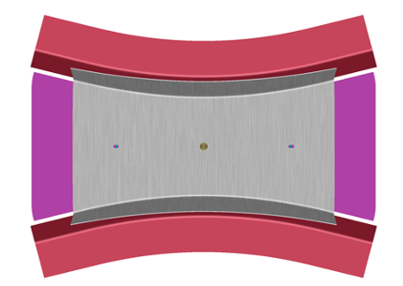
Fig. 2: Flanging tool & blank
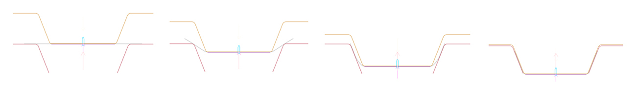
Fig. 3: Sectional view of flanging operation

Fig. 3: Blank in pre-heat position, showing the location system defined in AutoForm
The customer was very impressed with the preliminary tooling strategy, expressing confidence in the meticulous detail, and awarded the project to SATE.
Another advantage of designing the tool in AutoForm was seamless collaboration with the toolmaker. Establishing crucial details up-front – such as the forming angle, blank location, and punch radius – expedited the creation of the final tool. The SATE team were then able to re-run the simulation using the CAD model provided by the toolmaker for secondary validation. If the results matched or exceeded what the SATE team achieved in their preliminary simulations, they would approve the tool for manufacture.
To secure the blank in place during forming, the SATE team placed a fixed stud in the center, with two slotted cutouts on each side to accommodate the expansion which occurs during heating. Once the pressure plate and punch were both in contact with the blank, displacement force was applied to gradually draw the part over the flanging steels. By maintaining a firm grip, the tool achieved the desired curvature in both directions, preventing bowing in the center of the blank that was observed with other methods.
Results
Following the first forming run, SATE conducted basic measurements to assess the angle, thickness, and flatness of the part. Several height measurements were also taken to verify that both flanges were drawn at the same rate. These preliminary measurements, along with a CMM check to verify surface profile confirmed that the first part off the press conformed 100% to the customer’s requirements.
This shows how SATE’s approach to innovation, and embrace of approaches and technology, was able to drive positive results for customers.
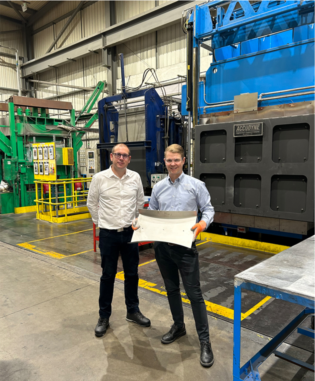
Fig. 4: AutoForm’s Tom Scott with SATE’s Darren Godfrey and the final part.
See part three here.


?")


