
By name, a Digital Process Model implies a digital representation of, in our case, a Stamping Manufacturing Process. This Digital Process Model includes a material card, tool geometries, operations, work being done in these operations, a blank, and a representation of your checking fixture. These are the primary components needed to run a simulation, which will then provide some critical result variables to help us evaluate the simulation.
So, why is this important to you as the user? Coming from a Tool and Die/Manufacturing background, my innate culture tended toward reactive behavior. As a result, we tackled our problems by spending money and working harder. With the tools now available, you can adopt a proactive mindset, spending far less money in the virtual world than you would in the physical world.
What is a Digital Process Model in Upstream Engineering?
By definition, a digital process model requires a physical item in space (your final part), in software form (your simulation), and data that links the two together (your results). To add value to the digital process model with good data links (or matches), the inputs should be individually cross checked with the results. The AutoForm Accuracy Footprint concept is very useful to validate this digital process model.
Following is an example of how to create a Digital Part Buyoff Process Model. The activities described below are all part of the Accuracy Footprint methodology which covers the 8 cornerstones of an accurate process model.
1- Accurately represent your intended tool geometries throughout the entire manufacturing process. (Geometric Cornerstone)
Draw Dies-
- Whether you are generating your geometries in CAD or other software, the intended surfaces and punch openings should be clearly represented in the proper orientation.
- The draw die should also be expanded to account for the material contraction (Young’s Modulus- modulus of elasticity in tension).
- The draw beads should be optimized to equally distribute plastic strain to the extent possible.
Line Dies-
- Trim Dies- These tools must be representative of your intended manufacturing process. This would include generating your Lower Post, Upper Pad, Trim Steels, scrap cutters, and pilot locations (if necessary).
- Flange dies and secondary forming operations must similarly reflect your intended manufacturing process. This includes any wiping and ironing you intend to incorporate into your machine clearances.
2- Accurately define the materials. (Material Cornerstone)
- Arguably the most important process inputs are the material properties. We have come to recognize this is the best $150 your company will ever spend. In just two days, your local laboratory will carry out tensile tests and provide your team with up to the minute data on your material properties. It’s important to understand that simulation relies on more than just formability. Subsequent Compensation and Robustness Strategies against the variance of material properties must reflect these process windows.
3- Ensure the manufacturing process is sound and capable of meeting your company manufacturing criteria. (Process Standard Cornerstone)
4- Accurately represent friction between the tools and the sheet. (Tribology Cornerstone)
5- Ensure measuring stations reflect the intended GD and T configuration. (Evaluation Cornerstone)
6- Ensure simulation process parameters adhere to the recommended standards. (Simulation Standard Cornerstone)
7- Ensure your optimization loops (restraining forces, blank, travels, pressures, etc.) are physically achievable in your tool design and production equipment. (Material, Geometry, Tool kinematics & Process Cornerstone)
8- Account for and simulate all the influential noise variables in your process. (Robustness Cornerstone)
- Mitigate the influential noise variables.
- Compensate for dimensional accuracy (mean shift once Cp has been established).
- Re-validate your Cp (Process Capability) and Cpk (Process Capability Index) with the compensated geometries.
Using this example, most of our simulations do not meet the criteria of a digital process model. What’s lacking? Simply put, our simulation represents a process point, not a process window. It will show you where a given point sits relative to your buyoff criteria. (See Figure 1)

(Figure 1- Process Point)
In the example, you appear to have a safe simulation. But does this mean your simulation is in the clear simply because the point falls within the window? The short answer is no! What we still need to consider are the effects of the noise variables on your simulation.
What are noise variables?
Noise variables are variables that are difficult or impossible to control at the design and production level but can be controlled at the analysis level, such as lubricant and material variation. A noise variable will have the nominal value as specified by distribution, which follows the distribution exactly.
With a background in manufacturing Prototype and Production Tools, I spent 35 years of my life in all facets of a typical die manufacturing shop. In all that time, I’ve never seen a better opportunity to change the face of Engineering and Manufacturing of Sheet Metal Parts. Some even consider this a paradigm shift beyond any in the Tool and Die Industry since the implementation of CNC machines 40 years ago.
Before we begin talking about these tools, we should recognize where the biggest “unknowns” reside in the manufacturing process.
We all understand what it takes to engineer and manufacture stamping dies, so we can estimate the cost for this portion of the process. What we don’t understand is how much time, rework, and money it takes to demonstrate Process Precision (Cp) and Dimensional Accuracy as a part buyoff criteria (Cpk). And therein lies the area of biggest risk because we cannot calculate or even estimate the cost or total re-work to sell the tools. If demonstrating Cp and Cpk before selling dies is your biggest problem, I urge you to continue reading. We will be delving into some worthwhile details to consider.
Please understand that other noise variables (uncontrollable) may exist in your stamping environment (e.g., the effects automation may have on your dimensional accuracy) that are not accounted for in this example. It will be up to you to identify and capture this variance, then include it in your Robustness Simulation to analyze its impact on the overall process.
When considering the noise variables, we can run a “Robustness” simulation that accounts for all the noise in your material properties, friction, and blank positioning, giving us a process window. (See Figure 2)

(Figure 2- Process Window)
So, what does this mean to the Formability Engineer?
If Figure 2 were representing thinning criteria, it would demonstrate that the process point is healthy. But when considering the material variation, it exhibits failure about 20% of the time due to the variation in material properties.
To be clear, this “failure” (Cp/Cpk) would apply to any result variable — whether formability, thinning, or springback.
Now we’ve identified that the simulation is not as healthy as we thought, we have the opportunity to tackle the issues before we start machining the tools.
So, how do we go about addressing this?
While I can’t answer this specifically, I can tell you there are many ways to influence the overall variance in your process, including:
Reducing the overall variance
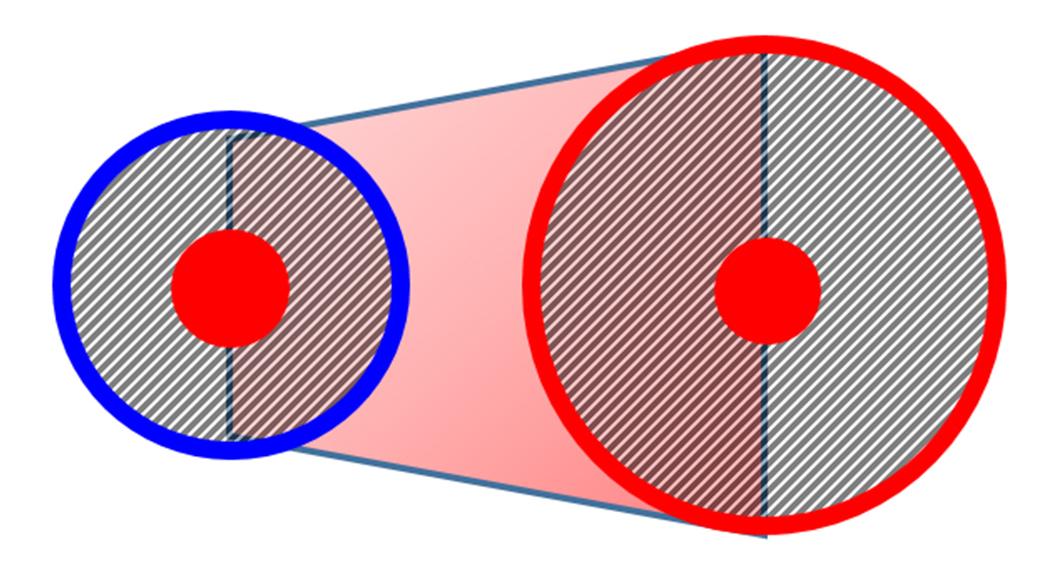
Figure 3- Overall Variance- Before/After
Centering your process point
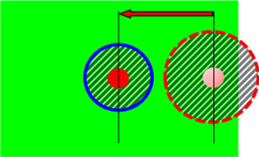
Figure 4- Centering your Process
I don’t know about you, but in my previous life, we would have paid dearly to have this information upfront. Although we only manufactured stamping dies, we never knew how much it would cost to achieve a part buyoff. When we got the initial panels on the CMM machine, we had just started to scratch the surface of understanding how much money was yet to be spent. I will try to explain with the aid of some images.

Figure 5- Cp<1.67 demonstrating inconsistency in your process
As Figure 5 demonstrates, a non-controllable variance can put the company in a precarious position. Now we cannot simply perform a mean shift on the tool surface because no matter what we do, we will never get the samples to fall within specification. First, we must root cause and mitigate the inconsistency. Furthermore, I promise you that if you were to ask three of your plant superintendents/managers about the cause of the issue, you would get three different responses.

Figure 5.1- Cp>1.67 demonstrates a consistent process- But a non-conforming Cpk
This example (Figure 5.1) demonstrates a consistent Cp (repeatable process), but a non-conforming Cpk (process is not centered). This is not a bad situation for the company. Why? Because we have a stable process (Cp>1.67). By spending a bit more money, we’d have a high probability that making a mean shift to the tool surfaces would rectify the dimensional integrity of the parts being produced.

Figure 5.2 Cp/Cpk>1.67 demonstrates a consistent process (Cp) and Conforming Process Capability Index (Cpk)
Unsurprisingly, working in a virtual environment is less expensive than working in a physical environment. If we now have a representative Digital Process Twin, the question remains: Why would we not consider leveraging the Robustness portion of Sigma to evaluate the Part Buyoff criteria?
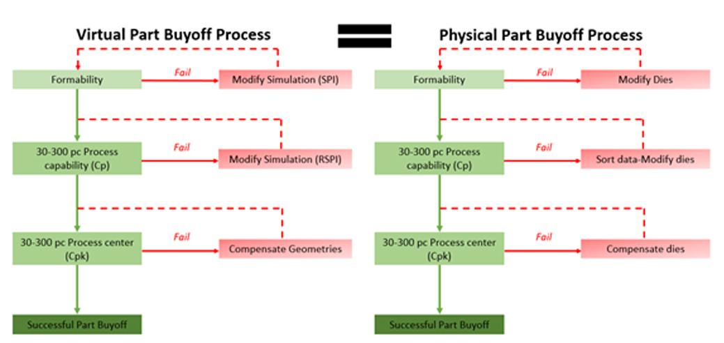
Figure 6- How the Virtual Part Buyoff Process would look compared to the Physical Part Buyoff Process. (Click to enlarge)
If the average cost per quality loop in Die Tryout for an average part is in the neighborhood of 50,000 USD, it seems reasonable that we would like to mitigate these additional costs because in most cases, these are un-budgeted funds in your contracts. If we decide to take this approach, we can reasonably deduce that a quality loop in the virtual world is much less expensive than the physical world.
Is your company concerned with the risks involved in demonstrating your tool capabilities (Cp/Cpk) as it relates to your Part Buyoff requirements? Please feel free to comment.


?")


