Looking Under the Hood of the Accuracy Argument
An accurate simulation is one that predicts the result of an experiment correctly. The accuracy footprint is a concept taught by AutoForm, which can be applied to any sheet metal forming software to determine how accurate your simulation is. What it does is provide you with a systematic process to check the quality of all the inputs. You can then find any differences to reality and reconnect an “inaccurate” result to the stamping process.
In practice you hear, “Ok, here is the simulation result. There is the result from tryout (or production).” If the resulting part does not match the simulation result then you can be sure something is different in tryout. In our experience 4 out of 5 cases in tool tryout did not fully reflect the engineering intent and one or more important process details in tryout did not match the simulation set-up. As a troubleshooting process our accuracy footprint model proves this time and again.
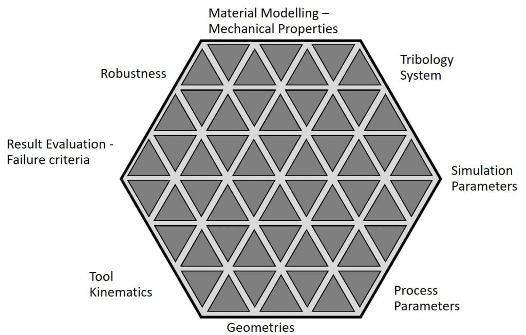
Accuracy Footprint Diagram
Troubleshooting with the Accuracy Footprint
The basic principle is that if the experimental set up and the simulation set up are identical then the result will be identical as well. This is the foundation of the footprint. Within the accuracy footprint itself we then look into the actual quality of the footprint. In doing so this allows us to examine how well the simulation and experimental input correlate. Therefore, the footprint diagram becomes a symbolic representation of the quality of the input. As an organic process the footprint itself grows in size when a larger number of parameters match.
Let’s consider the different aspects for the entire stamping simulation to understand the diagram. As we examine it we’ll move around clockwise.
It starts with material and mechanical properties. These consist of elements such as the R-values, yield strength, tensile strength, material model, blank thickness, etc. These are represented by the individual triangles in that section, which as a whole comprise “Material Modelling – Mechanical Properties.”
The same occurs for the Tribology System. That block in the footprint consists of different aspects which, in their totality, should represent the complete tribology system seen in reality.
Going around the diagram you expand the accuracy footprint to include your Simulation Parameters, Process Parameters and Geometries. The last of these looks into the geometries of the level of the punch, the binder and the die. But you can also examine it at the level of the addendum, the radii and wall angles, etc. The diagram shows that within each block you end up with different aspects and levels of what should be taken into account.
The next part is the Tool Kinematics, then the Result Evaluation and Failure Criteria. Lastly, the diagram features the Robustness part of the footprint.
All of these are aspects of simulation but represent a complete stamping process in all its detail. One must understand, all these aspects need to be defined during the experimental set up, just as they were set up for simulation.
Realistically, you’ll also work with your Material, to see if you have the proper blank size and thickness, for example. You’ll want to make sure the Mechanical Properties are the ones we want to have.
In reality, you’ll work around the accuracy footprint to the tribology system like before. Do we have the right amount of lubricant? Is the surface roughness of the blank and tools as expected? This should all be done in the experimental set up in tryout. Troubleshooting is too late.
Tryout has all these details to observe during their own set up. They work through the accuracy footprint. They’ll look at the Process Parameters, such as the positioning, the tool movement, the forces, etc. Continuing to work the diagram clockwise they’ll get to check their Geometries, do they have the correct radius, or correct wall angles, etc.?
Now they get to the Tool kinematics part of the footprint. They’ll set up the tool movements, and verify the cam angles etc.
Arriving to the Results Evaluation and Failure Criteria splits and wrinkles are easily detected, but going deeper, we must look for things like skid lines or springback.
Lastly, at the Robustness part of the footprint you will have to look for repeatable results. It’s not one lucky shot, rather the reliable serial production of the part a production process set-up aims for.
The Problem of the Reduced Accuracy Footprint
If one or several parameters do not match then you have a reduced footprint (below diagram). Consequently, you can expect deviations between simulation results and experimental results. Differences in input on either side is why the results don’t match.
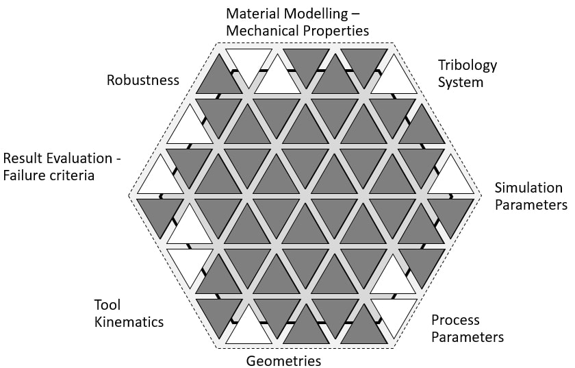
Reduced accuracy footprint diagram
“Right or wrong” becomes a non-issue. The method allows us to question “Is it really identical, yes or no?” If results are different, then you will always find there is a difference in the tryout setup. The role of the tryout process at this stage is to create a perfect match with the digitally engineered model. The footprint represents a methodology to systematically go through every parameter defined on both the simulation setup and the tryout setup, side by side, so you can troubleshoot by verifying that one coincides with the other. This process is illustrated in the practical examples described below.
AutoForm has a guideline we strongly recommend you to use, which systematically defines your simulation settings. It’s naturally easier to modify the simulation than to modify anything in tryout.
Case Example Door Inner OP Drawing
A “Door Inner OP Drawing” saw a split occurring in tryout in the lower corner. This was not observed in simulation so we returned to the accuracy footprint and recognized the blank thickness settings did not match. In simulation the thickness was 0.98mm but in tryout they had used a 0.80mm. Because a different blank was used in tryout, it created the mismatch between digital set up and experimental set up.

Now, in order to verify the result the simulation was re-run with the blank thickness actually used. The resulting simulation predicted splits in that area. Simply put, having a matching input between simulation and experimental set up provides results which match. And this simulation set-up may be used to find a solution for the actual forming problem – namely the split in the lower left corner.
Case Example Hood Outer
Another good simulation was mismatched in tryout by a split in the corner.
Yes, there was some thinning in simulation but nothing major. Upon investigating it through the accuracy footprint we found that the die was barely polished which created excessive thinning and splits. They compensated by adding oil. In simulation they had used a polished tool surface when the roughness in reality was higher. The default amount of lubricant was 1 gram per square meter but they used three grams in reality to decrease the amount of friction. Even when the sheet was practically floating in lubricant it didn’t help resolve the splits.
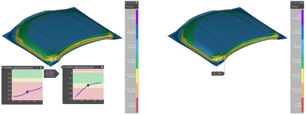
As an exercise the digital set up was changed to incorporate this high die roughness and high lubrication amount – and the splits were correctly predicted. While the study showed you could influence the thickness in that corner by increasing the amount of lubricant unfortunately this effect was insufficient to compensate such a high surface roughness. The solution to the problem was that tryout needed to polish the die and work according to engineering’s initial plan.
Changing the digital set up to match tryout just digitally predicts splits in the same area. But the exercise of matching an unsuccessful tryout set up through simulation should be considered an “academic study.” Good input on both ends, or bad setup on both, once the digital and experimental set up match – the simulation and tryout result perfectly match each other as well.
The goal is not to match your simulation to a bad tryout setup, but to match your tryout to a green simulation that predicted safe parameters. This accuracy footprint therefore is not just a symbolic representation. It’s a thought process for successful engineering.
We also must bear in mind, comparing ONE experimental measurement and ONE simulation result does not allow a valid conclusion regarding accuracy. And even if you have just one real panel measurement – all AutoForm users (!!) have the chance to easily generate a point cloud for simulation results. So every AutoForm user has the chance to upgrade to a “real” accuracy assessment! We’ll go into this more in our upcoming accuracy series.
In its totality AutoForm’s Accuracy Footprint concept provides a proven framework to systematically analyze the root cause of most discrepancies between measurement and simulation. This is not only helpful for quickly identifying the cause of a mismatch, but also offers a tool kit to speed up tryout AND for future improvement of simulation set-ups.
By Dr. Bart Carleer, Technical Director AutoForm
For interested readers, you may also enjoy this video of the Accuracy Footprint Webinar presented by Dr. Bart Carleer on May 20, 2020:
*Background cover background: courtesy Volvo Body Components.


