
Which tryout activity consumes the most skilled resources?
If your answer is “die spotting,” then you are correct! In this blog post, Sameer Chudnaik, Application Engineer at AutoForm India, discusses how different equipment parameters, particularly tool deflection, impact die spotting and how digital engineering through frontloading the manufacturing process can reduce overall tryout time.
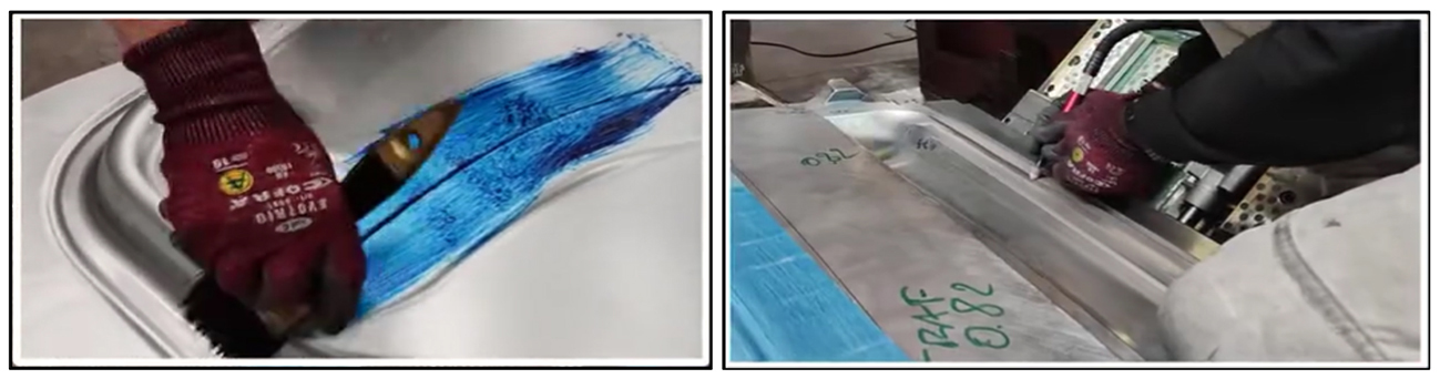
Fig 1: Manual spotting activities during tryout
Problem Statement
Approximately 35% to 40% of tryout time is spent on initial die-spotting activities. Skilled resources specializing in quality maturation are often overburdened, especially for critical parts. As a result, quality maturation activities may extend beyond the planned timeline.
Causes and Mitigation Through Process Improvements
Die spotting has always been a challenging process, as its results are affected by multiple equipment and process parameters, including press parallelism, machining variations, and inaccuracies (such as worn-out cutter during machining). However, this article focuses on the impact of press and die deflection.
During sheet deformation, the load from the motors continuously deflects the tool, ram, and bed. The highest press force typically occurs at the bottom dead center, making it difficult to calculate die deflection values using thumb rules. Die deflection depends on several parameters, including:
- Draw force on the die
- Percentage of the press area covered by the die
- 3D die face balance
- Die rigidity
This deflection effect must be compensated through simulation to avoid additional spotting time in tryout.
Understanding the Impact of Deflection
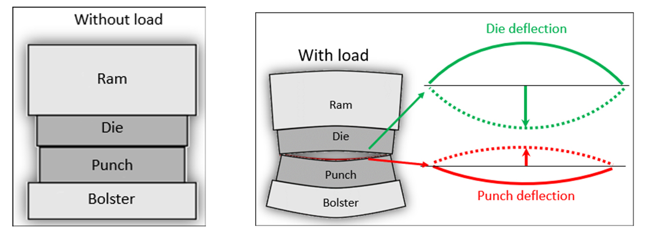
Fig. 2: (Left) When dies are closed (at BDC) without any load, the upper and lower dies have direct contact with one another. (Right) When dies are closed (at BDC) with the application of load, the upper and lower dies go into deflection.
During tryout, non-uniform sheet holding conditions arise due to deflection. The tryout engineer applies blue on both sides of the sheet and begins spotting the dies using grinding machines, which is a manual and skill-dependent process. It can take significant time to precisely match the upper and lower surfaces to complete the spotting process.
To minimize manual spotting efforts, many companies adopt a specific approach :
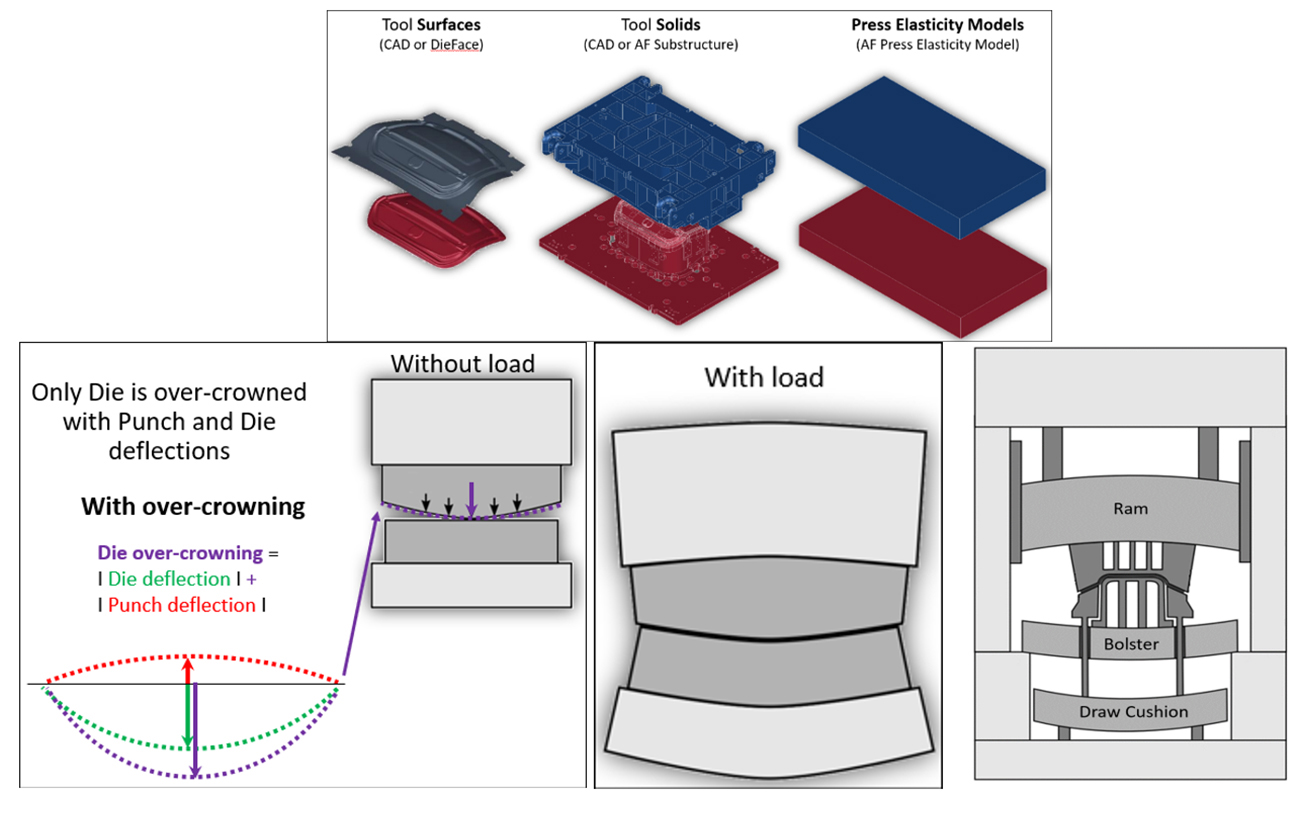
Fig. 3: Only the upper die is over-crowned to compensate for both punch and die deflections. The lower punch is kept as the master (no crowning is applied).
Thus, the die over-crowning formula becomes:
Die over-crowning = die deflection + punch deflection
Upon further investigation, die deflection was analyzed using inputs such as forming simulation files, tool solids from tool design, and elasticity models for casting and pressing. If a die design is unavailable, tool solids can be generated using AutoForm’s substructure generation model, as shown in the image below.
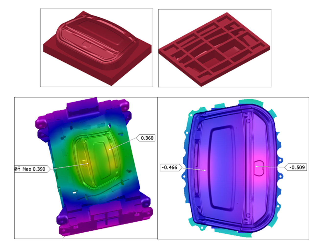
Fig. 4: Maximum deflection values of 0.4 mm observed in the upper die and 0.5 mm on the lower punch.
Some companies perform die-face over-crowning based on thumb rules. However, even if over-crowning is applied at the center of the tool, real deflection patterns often do not match this assumption. As shown in the right-hand image, the maximum tool deflection for a boot lid panel has occurred off-center. The actual maximum deflection point can vary depending on individual geometry and force distribution.
If over-crowning is manually determined in CAD software using the die center as the highest deflection point, it may lead to inaccuracies during tryout. Instead, advanced software like AutoForm is needed to calculate real tool deflection accurately. By simulating tool deflection, the results will generate the over-crowned surface best suited for milling.
Ultimately, it was decided to over-crown the upper die using deflection data from both the upper die and lower punch. The image below illustrates the over-crowned data generated using AutoForm, which is now ready for milling.
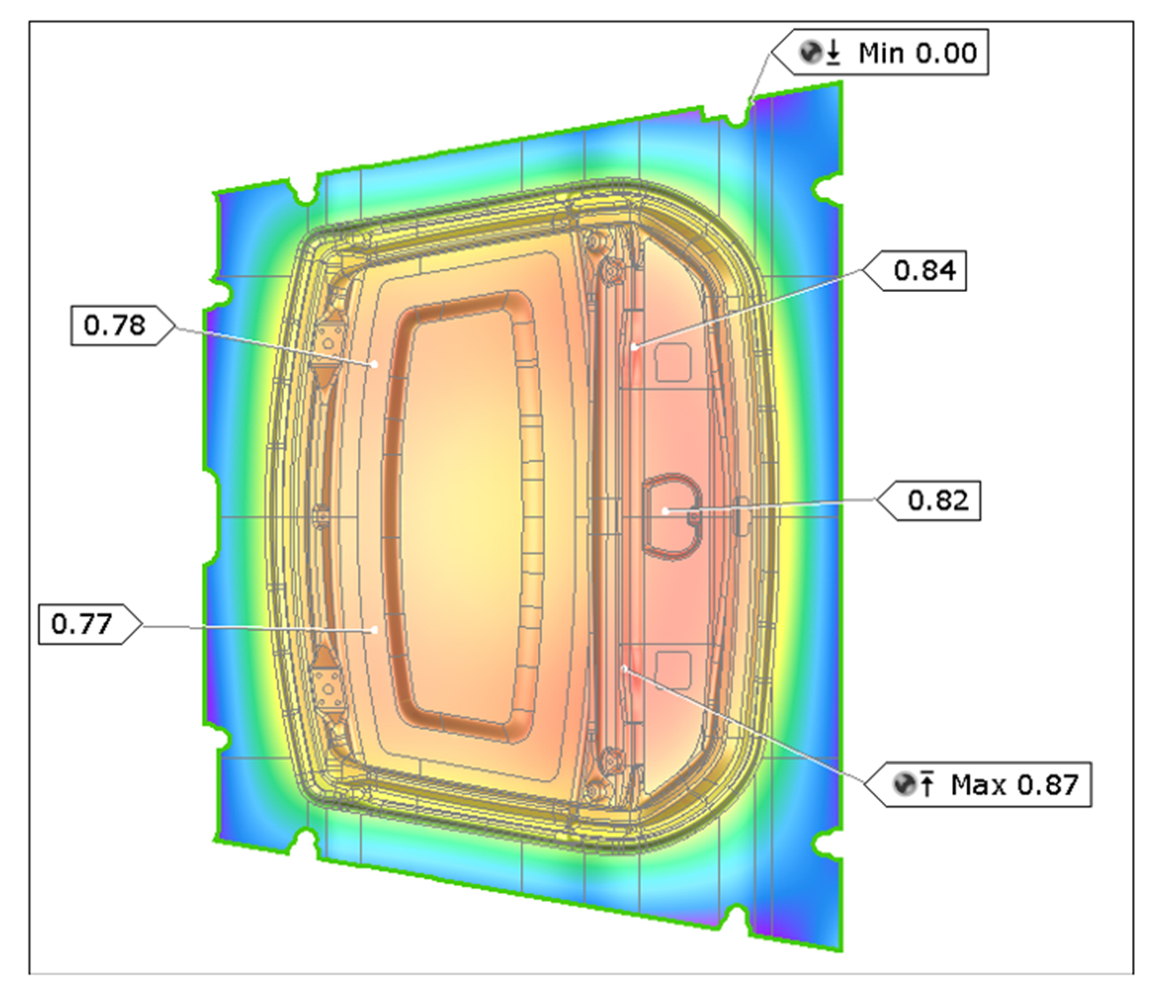
Fig. 5: Part ready for milling.
Benefits of Tool Deflection Analysis During the Engineering Stage
In a manufacturing environment, if an average part requires 12 man-days for draw die spotting, a 50% reduction in spotting time through tool deflection analysis can save 300 man-days annually for 50 parts. This significant reduction enhances overall shop productivity.
Additional Benefits: Lightweight Stamping Dies and Cost Savings
For further analysis, a comparison study was conducted to examine different die rigidity conditions and their impact on tool deflection.
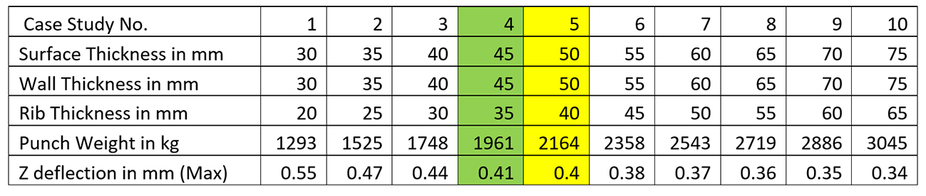
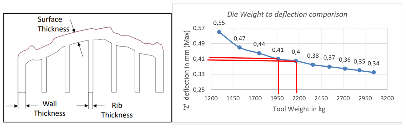
Most OEMs and die shops follow casting construction standards based on column 5, which results in 0.4 mm die deflection. Increasing rib strength (as shown in columns 6–10) increases die weight considerably but does not proportionally reduce deflection.
However, modifying the casting construction as per column 4 can reduce punch weight by 203 kg without significantly impacting tool deflection (0.41 mm vs. 0.40 mm, only a 0.01 mm difference).
Considering that AutoForm’s simulation time (including setup) is just 6 minutes per iteration, the 10 iterations in this study took only 60 minutes, leading to an optimized punch structure design.
Improve Efficiency and Reliability Through Casting Structure Enhancements
The case study below suggests that the embossed zone demonstrated higher deflection, which was reduced by adding a rib below this high-deflection point. Similar studies can be conducted for a variety of die structure conditions to improve casting efficiency and reliability.
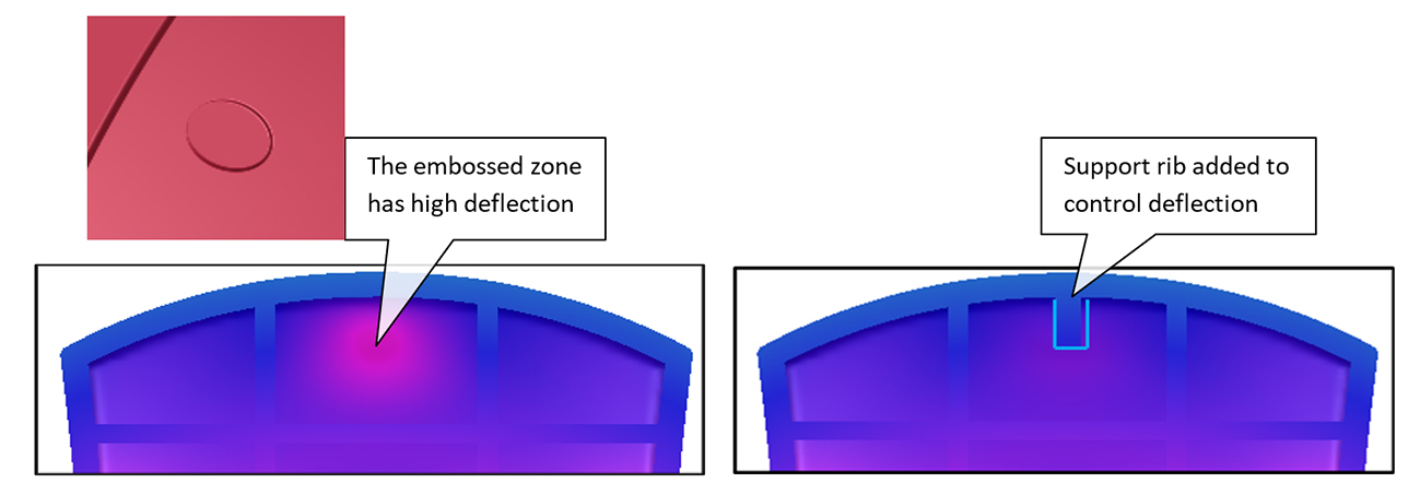
Fig. 6: Rib added below high-deflection point.
Without die deflection studies, achieving even 0.1 mm accuracy in die spotting during tryout is challenging for large surface panels. This process requires considerable time and depends heavily on operator skills.
Conversely, implementing changes during digital engineering provides greater flexibility and control over expected outcomes. By leveraging digital tools, companies can reduce overall efforts and significantly cut down tryout time, leading to improved productivity.


?")


