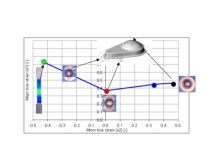
After the recent posts on failure prediction based on FLCs, several inquiries arrived through the blog and social media, regarding interpretation of other outputs for predicting failure modes. Commenters wanted to know the values, for various result variables, that might define the upper and/or lower limits, and how one interprets results to determine part/process feasibility. This brought to mind the fact that stamping engineers spend a major portion of every week analyzing the results from the simulation that they run and looking for any failures.
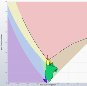 This often means switching between several result variables and reviewing result color scales plots looking for values that exceed the limit for each variable. Precisely what values constitute failure, is something that we can leave for a later (and possibly contentious) post. What does bear mentioning, right now, is how we can streamline this activity of applying specified limits for key result variables.
Issues based evaluation
In the past, a specialized “analyst” might have reviewed the FEA results and noted the issues in a report. Stamping process method planners would use the static report to interpret the issue and apply a corrective action to the suggested forming process; increase/decrease parameters such as draw beads, binder pressure, die and punch radii. In today industry, this high level of specialization is not the standard. In today’s stamping engineering environment engineers and planners act as their own simulation analysts.
Searching for areas that fail the various forming criteria is a time consuming task, one that is arguably not the best use of engineer, planners, or analysts time. Instead, applying the specialized skills of engineers and planners to define corrective actions to any found forming issues, is the best use of their time. Of course, applying the corrective action requires that we know where the issues are. If the task of finding the areas that might have issues could be sped up, the engineering process would go much faster.
Potential issues might include:
• Splits
• Wrinkles
• Draw-in
• Springback
• Surface Quality
• Product Performance
When attempting to find all the areas that might split in the part under a given process, there are a number of criteria that the engineers and planners should review to identify splitting potential. The most common might be FLC based criteria like Formability. However, applying only the FLC criteria can still fail to detect some specific types of failure. Failure by exceeding edge stretch, or surface cracks caused by exceeding bend ratio, or the accumulation of excessive shear are modes that are not predicted by looking only at the FLC for the part/process. It can happen that an engineer or planner might not look at a particular result variable for each iteration and could potentially miss a failure.

Issues flagged on the results semi-automatically make identifying failures easier, more time to focus on resolution
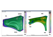
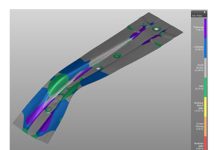
AutoForm-ProcessExplorer introduced an innovative feature with Issues Based Evaluation. Using an applied evaluation standard, AutoForm can compare the complete set of computed results to the full set of evaluation criteria, as loaded for the current design. Depressing the “find splits” button from the Issues interface within the Designer Window will create a list of the found areas and the issues at those locations. The user then reviews the areas and depresses “Accept” to accept the area and issue, as found. Once a found issue is accepted, the issue is stored with the design file and its location persists, and each location is checked to see if it still fails the standard. If changes to the design file result in the issue condition improving, the issue would update to show the improved passing or marginal status. If the changes do not improve the issue at that area, it will continue to show failing. In this manner the user is now freed up from having to “chase” issues and search manually for any improvement. The engineers time is now available to focus on the value-added task of improving and optimizing the process plan.

Now whenever a design file is saved under a new name, or cloned, the issues serve as a kind of failure history, capturing the status of any issue. If any of the output variables that are linked to a given issue type change for the better the issue will update, perhaps from the red colored icon to the yellow, warning icon. If the change is sufficient the issue type will change to green, indicating that the panel is now safe. If any of the output variables get worse you can also note a color change with green issues shifting to yellow or red.
Issues also are a key component to the great advance in metal forming process engineering, when this innovation is linked with AutoForm-Sigmaplus. The systematic process improvement method we have outlined in earlier posts, uses the issues detected to identify and analyze the part/process for safety. It is the resolution of defined issues that AutoForm-Sigma uses as a target when identifying the range of design input characteristics to modify and to what values.


