One of the most time-consuming and difficult-to-predict aspects of die build and tryout for progressive dies is the development and validation of the blanking cuts. Blanking is often a series of cutouts used to trim the flat coil material and define the edges of the final product. In most progressive dies, the edges of the product, regardless of their final orientation in the part, are trimmed while the coil of material is still flat. This “developed” blank line or “developed” trim line approach is preferred, as it does not require expensive cam units, but instead completes all the cutting of sheet metal direct—using the vertical action of the press.

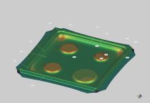
The part edge of many progressively stamped parts is defined while the sheet is flat, prior to forming the shape
During engineering of progressive dies, method planners and die process designers envision the shape that the part material will have prior to the forming of the part. This involves the practice of “unfolding” the part bend-by-bend until they have the flat pattern blank needed to define the perimeter of the part. Methods for determining the “developed” blank have historically utilized techniques of making paper, cardboard, and rubber models of the part, which the designer would flatten to describe the flat volume of metal that makes up the part.

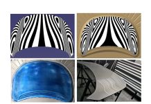
Bluing on the perimeter of the blank and formed part, in an attempt to identify where the blanking cuts need to move
With relatively straight bend lines, it is possible to reliably estimate the location of the developed blanking cuts by making elementary measurements of the finished part geometry, with additions and subtractions to the length of the 2-D section line based on the material’s bend allowance. The bend allowance for various bend radii, bend angles, and metal thicknesses has been used in practice for many years. However, if the part has any curvature to it or the shapes are more complex than bends along a straight line, the bend-allowance-based estimates will still vary in their accuracy once the die is built. For this reason, the blanking development that has been completed during engineering and design is regularly used as a threshold recommendation for determining minimum/maximum coil widths and pitch-but not necessarily relied upon for the machining and production of blanking steels for the final die.
Instead, time is commonly allocated in the construction process for the final in-press development of the blanking and trimming lines. Die construction might begin with the machining and build of the form stations, while the incomplete cutting and blanking steels wait. Tryout of the forming steels will commence using preliminarily trimmed and blanked sheet metal. Proposed blanks are sent out for custom laser or water cutting. Perhaps three or four of the best approximations of required blank size will be cut; those custom cut blanks will be fed to the forming stations and the resulting geometry painstakingly measured.

Designers will then adjust the proposed blanking lines to increase or decrease the blank size—moving the blanking lines in or out. More steel is sent out to be custom cut, and the process repeats. Some die makers say that it is common for the blank to be recut 10 to 15 times prior to arriving at a shape that suits the finished part. In some extreme cases, the blank could be cut dozens of times before the designers have to conclude that there is no developed blank shape that will deliver the finished part shape as required. When this happens, they would have to request a late product design concession to resolve the issue, or introduce a secondary trimming operation—which is most likely neither planned nor budgeted for.
Digital Process Planning
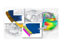
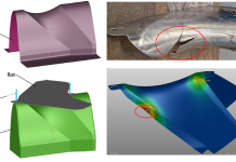
Advanced sheet metal forming engineering solutions can be used to provide trim and blank line optimization, which automates the simulation of a tool using the proposed trim line and the measurement of the finished part relative to a desired target curve, then proposes a new blanking or trimming curve—repeating until target threshold is reached. In most cases, after a handful of iterations the system will arrive at a blanking curve that is within a part-thickness of the desired target curve – or will prove to the designer or method planner that no stable process exists where a developed blanking line delivers the part boundary targeted.
The implementation of a trim line optimization solution combined with metal forming analysis, has allowed many tool shops to do away with the laser cutting and water cutting of preliminary blanks, and directly build the hard-tools; no more leaving the trimming steels machined while the form steels are used to hit developmental blanks. Instead, full tool tryout can commence immediately using as-engineered tools in the press. Avoiding any in-press blank and trim development saves days, if not weeks, in the typical progressive die engineering and build cycle.
When, at the time of tryout, the blanking or trimming lines seem to miss the target boundaries, feedback from users has indicated that often improper piloting of the sheet or fitting of the forming steels has been at fault. The trim lines can be left alone. They tune the forms to make the trim lines work, rather than attempting to refine both the cutting and forming stations simultaneously.
- What has been your experience with developed trim and/or blank lines?
- How much time would you save if you could eliminate in-press development?


