
Time is money! How many times have you heard this phrase? And how many times have you absently nodded along in agreement? Yamasei Corporation, a Japanese part supplier, was certain that time was a factor that could easily become an issue when facing increased expectations and requests for different kinds of outer panels. Lowering the quality to speed up the process was not an option, as the outer panels had to be free of surface defects.
Facing the challenge of an increasing number of products while continuing to deliver the same quality called for one solution: speeding up the post-process engineering while maintaining the same accuracy in predicting these defects. That way, countermeasures could be made early in the engineering phase where modifications are faster and much cheaper than in tool tryout.
However, Yamasei concluded that their conventional method for detecting surface defects was too demanding in terms of effort and time. This led to a case study to discover whether AutoForm could replace their conventional tasks to achieve the same quality goals in a far shorter timeframe.
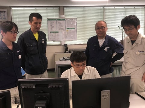
Fig.1: The CAE Team with Mr. Yamanaka, Director and Managing Officer (second from right) and Mr. Fujimoto, Manager of Stamping Engineering Section (second from left)
Prediction of the Surface Defect using AutoForm
In order to determine whether AutoForm could assess surface accuracy at greater speed than their conventional method, Yamasei first sought to verify whether the surface defects could be detected accurately. Given that surface defects are defined as very small bumps with a height of several tens of microns, they can only be detected by a highly accurate analysis setup. This setup involves following the Accuracy Footprint method to reproduce the exact process conditions of the real panel.
The analysis setup for the cross-sectional shape and position of the drawbead must match the actual panel. Also, the spotting area and non-spotting area must be distinguished in the analysis (Figure 2). As for the springback settings between processes, the excess constraints in the state of the initial panel inspection must be changed to free springback, so the actual state can be reproduced (Figure 3).
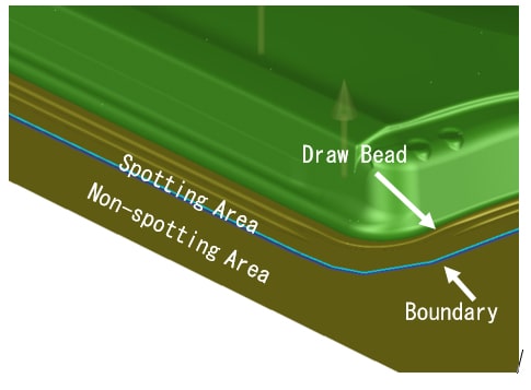
Fig. 2: Drawbead and non-spotting area
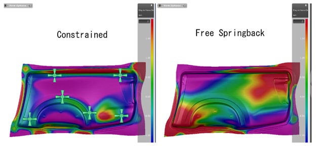
Fig. 3: Differences in springback with and without constraints
To assess the surface defects, Yamasei examined which result variables would best reproduce the sensory assessment (stoning) with the actual panel. The AutoForm result variables (the index for quantitative assessment) related to surface defects were (1) curvature case (positive or negative curvature), (2) three-point gauge, and (3) surface lows (stoning). Typically, surface defects are detected by comparing the panel before and after springback. This is because springback is often the source of the surface defect. However, concavities, recognized as a surface defect, are often hidden within the tool and product surfaces. In such cases, the comparison before and after springback may not be effective, or the measures for surface defect may be off. So the tool and product design surfaces were also assessed to ensure there were no concavities causing the surface defects on the panel.
Figure 4 shows the curvature case that detected the area with negative geometry in the product surface. Even if the concavity is detected in the same area of a formed panel, measurement is not required because it is a part of the product design.
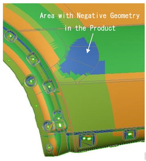
Fig 4: Assessment of product surface quality using curvature case
By analyzing the surface defect of a front fender and comparing it to the actual panel, the result variable “reference surface lows” showed the best reproducibility among three result variables used for the analysis. Figure 5 shows the results using reference surface lows to assess the surface defect occurring in all areas of the front fender. In all cases, the surface defect found from stoning was also successfully detected in the analysis.
In addition, the surface defect can also be detected by comparing the tool surfaces with the reference surface. The defect can then be assessed using curvature case or three-point gauge. Combining these assessments with the result variables makes it possible to detect the surface defect more precisely.
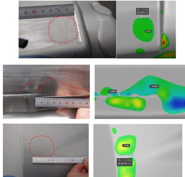
Fig. 5 Comparison of the predicted surface defects with the actual panel using reference surface lows
Expanded Use of AutoForm in Accuracy Verification
Now that the assessment of surface defects using AutoForm has been established, the next step was to assess the effectiveness of the solutions. Figure 6 shows measures taken against the surface defect occurring in a front fender. Excess metals during stamping, caused by a sudden change in addendum shape due to different flange depth, resulted in a surface defect. The effect of the overdraw modeling to relieve the sudden change in addendum and the gainer to increase a section length of addendum was verified.
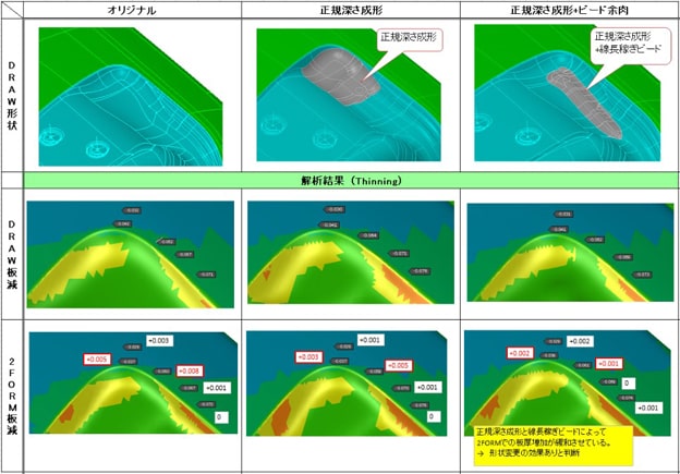
Fig. 6: Effectiveness of the measure against surface defect
Performing these verifications at the early stage of tool design makes it possible to not only identify surface defects but also find countermeasures against them – leading to reduced correction loops for the actual panel. Yamasei continues to optimize these front-loaded work processes to further shorten lead time and improve quality assurance.
About Yamasei Corporation
Yamasei is a manufacturer that designs and produces tools for sheet metal and resin dies, with its headquarters located in Matsuyama, Ehime Prefecture. Including the company’s beginnings with Yamamoto Seisakusho, Yamasei boasts a history of over half a century, dating back to the 1960s. Its customers comprise domestic and overseas automotive OEM and tier one companies, specializing in large difficult to form parts, such as body side outer panels and front fenders. Their three strengths are: the technology to fully utilize IT tools like CAD/CAM/CAE, the technology for high-precision machining in dedicated temperature and humidity-controlled environments, and experienced specialists.
Figure 7: Yamasei’s three strengths


?")

