Introduction
For decades, the simulation of processes such as stamping, cold and hot forming, and roll forming has greatly benefited the automotive industry. Today’s advanced software can replicate entire process workflows, including assembly simulation, with remarkable accuracy.
This case study highlights how one of our customers, a Tier 1 supplier to European OEMs, achieved a perfect assembly despite the constituent parts being significantly out of specification. A total of 30 parts made up the entire assembly. Although our customer has decided to keep their name private, they have given us permission to share their story due to the innovative way they employed assembly simulation.
Part Develops an Unusually High Springback
The supplier, working with a major OEM, faced a significant challenge with a 0.65 mm-thin floor panel made from regular steel (similar to the one shown in Figure 1).
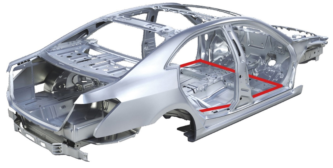
Fig. 1: Red lines indicating the assembled floor part.
The stamping operation was simulated for one part of the floor panel, revealing it was wildly out of spec. While the allowable springback tolerance was +/- 0.5 mm, the part exhibited a springback of 6-7 mm (11mm on the opposite side) —over 10 times the permissible limit. This deviation was critical and was later confirmed during the first trial runs.
Initially, it seemed that the only solutions were to re-engineer the part or modify the die. However, this unusually high springback presented several challenges.
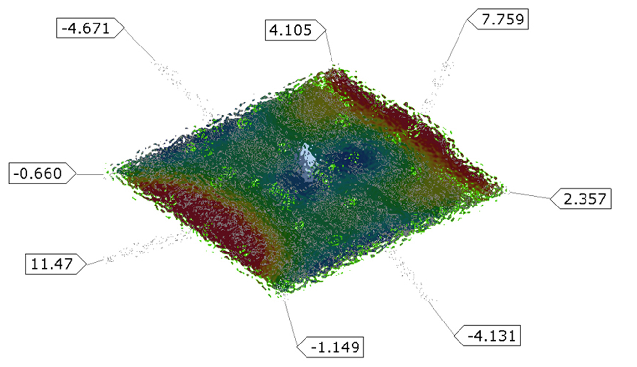
Fig. 2: High springback on the single panel of the cabin floor subassembly.
Uncertain Rectification Timeline
Smaller springback values can usually be rectified within a predictable timeline. However, in this case, the high springback meant that engineers could not estimate how long it would take to correct the part. Milling the die could take days to over a month, with no guarantee of success.
Die Milling Restrictions
Milling the die to reduce the springback posed another challenge. The gainers were smaller than the 7 mm springback, so they would have to redesign the tool or risk losing the gainers during milling.
Curved Tool Requirement
To compensate for the 7 mm springback, engineers would need to modify the surfaces of the die, turning flat surfaces into curved ones. While curved dies can technically create flat surfaces, this approach is unconventional and unreliable. Moreover, there was a risk of reversing the springback direction, which could have disastrous consequences.
Transitioning to a curved tool and milling deeper than usual could result in irreversible damage to the die. If the springback shifted in the opposite direction, the die might need to be scrapped, incurring costs of around USD 150,000 and causing delays of three to four months.
Solution: Assembly Simulation
Industry experts understand that stamped parts made within tolerances do not necessarily guarantee an accurate assembly. Green parts (within tolerances) can still lead to a red assembly (outside tolerances).
Before making any changes, the engineering team wanted to try an assembly simulation with their out-of-spec floor part to see if it could generate a green assembly.
A few years ago, assembly simulation was not possible. However, modern software now allows engineers to build virtual assemblies from multiple parts, even if they were made using different processes such as hot/cold stamping and roll forming.
Surprisingly, the assembly simulation revealed that despite the floor part being out of tolerance, the overall assembly would still meet the client’s specifications. The supplier followed three steps to ensure accurate results:
Step One: Build The Assembly Line using CAD-0 Parts
The engineers first simulated the real assembly line using nominal geometries. This preliminary approach is useful to verify the pilots, clamps, joints, and other components of the assembly line. They ensured that all steps were accurately represented and that no collisions occurred.
Step Two: Replacement of CAD-0 Data with Forming Simulation Data
Next, to increase the overall accuracy, the team replaced the CAD-0 Data with actual data from the forming simulation. The constituent parts were made using different processes.
Forming simulation data was available for both hot and cold stamped parts. Data for roll-formed parts was imported from another software by importing the mesh and expanding it to conduct the simulation. The simulation was performed to determine the residual springback after assembly. The results indicated that the final assembly would meet the client’s specified tolerances.
Step Three: Use of STL Data (Actual Part Geometries) for Result Validation
To validate the results from step two, engineers used actual part geometries obtained through 3D scanning. The use of STL data ensured that no detail would be missed in the simulation. The results confirmed that the assembly would be within the required specifications, even if the individual parts were not. Simulation results show that the maximum deviation of the floor assembly will be less than +/-1mm (see Figure 3)
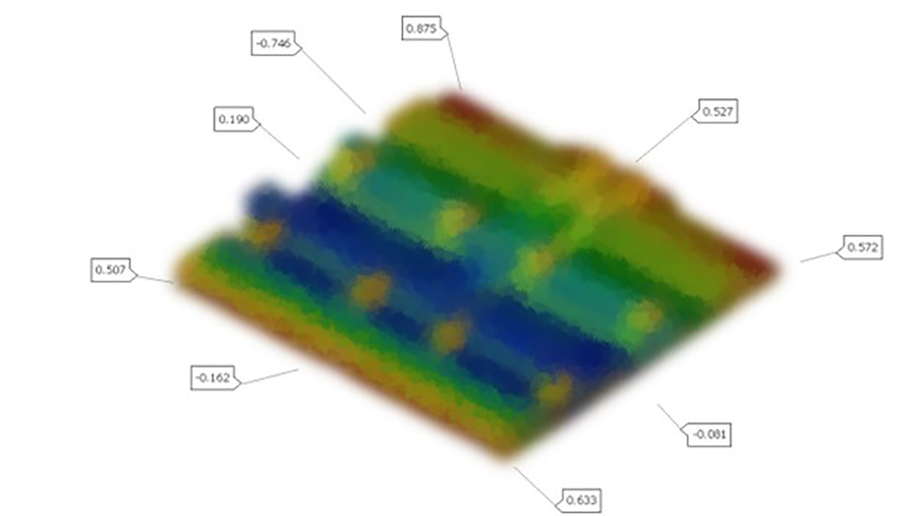
Fig. 3: Simulation results on complete cabin floor assembly (30 parts)
Benefits
Simulation success was followed by success in reality, as the assembly simulation accurately predicted the results. The simulation eliminated the need to correct the springback of individual parts to achieve a successful assembly. The measurements made on the real floor assembly have confirmed a close correlation with the simulation results. (see Figure 4).
The following benefits were derived from using assembly simulation in this case:
Eliminated Compensation Workflow
The supplier’s engineering team initially sought a solution to address the significant springback issue. However, assembly simulation showed that the parts would be pulled into tolerance during assembly.
The results saved the engineering team from having to compensate for individual parts. The supplier avoided a compensation workflow and its associated tryout loops, resulting in time savings of over a month by preventing recuts.
Negligible Simulation Cost
With 100% digitalization, engineering teams can simulate any scenario without worrying about the costs involved.
In this case, the team assembled a range of parts from different manufacturing processes. The history of stamped parts from the forming simulation was preserved, enhancing the accuracy of the assembly simulation.
The creative freedom led to the discovery that not all parts needed to be brought into tolerance for a successful assembly, solving a previously unsolvable problem with an innovative solution.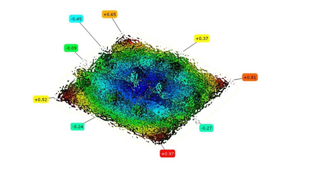
Fig. 4: Measurements made on the real floor assembly
Ability to Import Parts from Other Simulation Software
Most parts in the assembly were imported from the AutoForm software, while roll-formed parts were imported from another software. A common interface can be created between the two software programs to exchange historical and form-related information. In this case, however, only the geometry was considered.
At the same time, if real parts are available, they can be 3D scanned, and the resulting STL files describing the surface geometry can be imported into AutoForm Assembly.
Cost Savings from Avoiding a New Die
Milling compensation guesswork and the transition to a curved tool could have resulted in rendering the die unusable, with no possibility of repair by welding.
This would have necessitated the creation of a new die, with conservative estimates putting the price at USD 150,000. Eliminating the need for compensation avoided the time, effort, and cost of obtaining a new die.
Strengthened Supplier-OEM Relationship
Successfully delivering parts within the OEM’s tolerance specifications, despite initial challenges, enhanced trust between the supplier and the OEM. It demonstrated the supplier’s competence and reliability, potentially attracting more business from this and other OEMs.
Conclusion
In conclusion, the Tier 1 supplier’s innovative use of assembly simulation proved transformative, enabling them to build perfect assemblies from parts that were significantly out of specification. By simulating the entire assembly process, they bypassed the need for costly and time-consuming part re-engineering, along with potential delays and expenses. This approach not only saved the company substantial resources but also strengthened its relationship with the OEM by delivering on their expectations. This case study demonstrates the value of advanced simulation technologies in overcoming manufacturing challenges and highlights their potential to revolutionize traditional fabrication processes.


