
Abstract: This paper analyzes oil stone line break defects at the A-pillar position of the front fender, proposes principles for defect identification and generation, and reduces surface defects in first-produced parts by compensating NC processing data across the full process. Actual production results show that these defects can be effectively reduced by predicting them in advance through AutoForm simulation and applying corresponding compensation in the NC data.
Key words: line breaking defect, defect identification, generation principle, advance compensation, Real part verification
0 Introduction
As a means of transportation, automobiles have gradually become embedded in all aspects of daily life, including commuting, travel, and passenger transport. With rising living standards, consumers now place higher demands on vehicles, including exterior styling, interior space, and intelligent cockpit features. Among these factors, exterior appearance modeling is one of the most influential in attracting consumers.
When appearance parts contain defects such as line breaks, shadowing may still be visible after painting, which directly affects perceived vehicle quality. Based on production experience, line break defects are mainly concentrated at the A-pillar and B-pillar areas of outer door panels, the A-pillar area of fenders, and the C-pillar area of side panels.
The inspection method for detecting line break defects on sheet metal parts involves using a 100 mm × 10 mm × 10 mm oil stone to polish and mark lines along a specified direction on the appearance surface. A continuous line indicates no curvature defect, while a break in the line indicates a surface curvature defect. Line break defects on a front door outer panel and at the A-pillar position of a fender are shown in Figures 1 and 2, respectively.
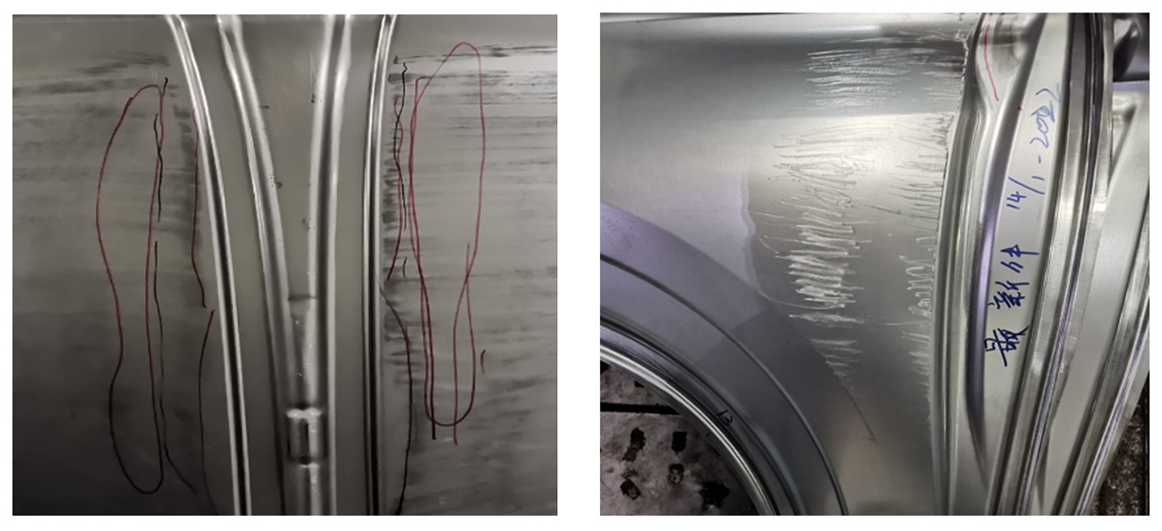
Fig. 1: (left) Break line defect of the front door outer panel
Fig. 2: (right) Break line defect of the A-pillar position of the fender
1 Defect Identification
Panel formability is analyzed using AutoForm simulation, which provides parameters indicating whether the part is fully formed. According to common industry standards, the evaluation criteria for passing the Class-A area simulation stage of an outer panel are as follows: minimum thinning ≥ 3%, major strain ≥ 0.03, minor strain ≥ 0, minor stress ≥ 1.1 × yield strength, and a surface parameter ≤ 0.03 mm when marking a 100 mm line.
Due to product modeling and process constraints, achieving all these criteria simultaneously is often difficult. At the technical evaluation stage, when several parameters fail to meet the standard, the probability of line break defects in the produced parts increases significantly.
Taking a front fender as an example, forming parameters were analyzed as shown in Figures 3 to 7. The material is CR240 with a thickness of 0.7 mm and a yield strength of 256.3 MPa, corresponding to 281.93 MPa at 1.1 × yield strength.
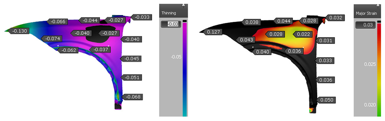
Fig. 3: (left) Minimum thinning
Fig. 4: (right) Major strain
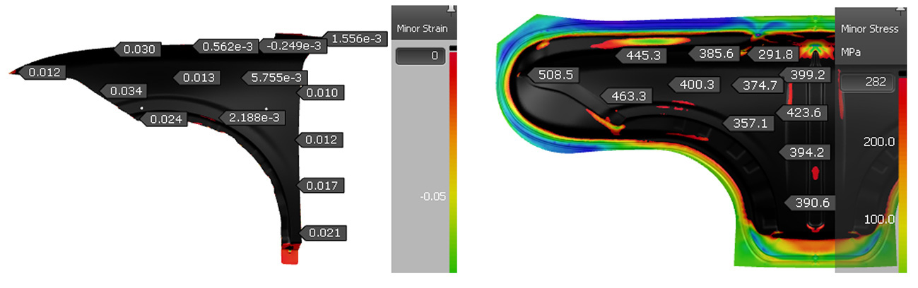
Fig. 5: (left) Minor strain
Fig. 6: (right) Minor stress
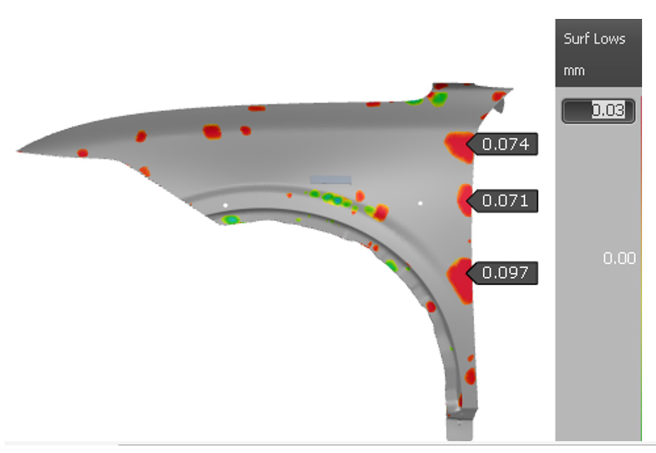
Figure 3 shows that the minimum thinning in the central area does not reach 3%, which does not meet the standard. In Figure 4, the major strain in the central area does not reach 0.03 and also fails the standard. Figure 5 shows that the minor strain across the entire Class-A area is greater than 0, which is acceptable. In Figure 6, the minor stress reaches 282 MPa and meets the requirement. However, Figure 7 shows surface defects exceeding 0.03 mm in three areas, which does not meet the standard.
Among the five evaluation parameters, two meet the requirements while three do not. Due to limitations in product modeling and process design, this analysis indicates a high probability of line break defects in the actual production parts.
2 Principle
Line break defects occur when parts are insufficiently drawn and springback is released after trimming. Surface defects observed in later processes originate from hidden risks during drawing and are amplified after trimming.
Assuming the A-pillar fillet connection area of the fender is drawn, springback amplification after deep drawing causes deflection at the joint surface. Under the overall springback trend, different regions rebound by different amounts, leading to slight surface distortion. The resulting twisted curvature is shown in Figure 8, and this distortion ultimately manifests as a line break defect on the part, as shown in Figure 9.
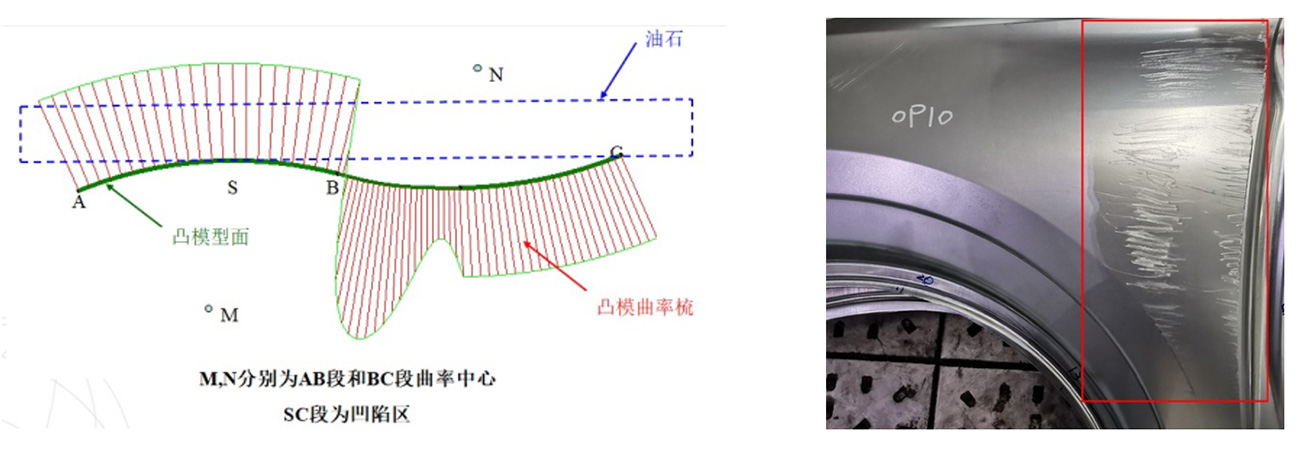
Fig. 8: (Left) Twisted curvature
Fig. 9: (Right) Fender line break defect
3 Pre-compensation
Optimization of line break defects is divided into two steps.
- During addendum design, counter bars can be added to promote more uniform sheet tension, and drawbeads can be deepened to increase holding force. These methods are shown in Figure 10.
- When surface quality parameters still fail to meet standards, NC processing data can be compensated to reduce surface defects. Compensation should be applied to both upper and lower tooling across the full process, as shown in Figure 11. The dotted line represents the original data, and the solid line represents the compensated data.
The compensation region typically ranges from 30 to 50 mm, depending on defect location and extent. Previous project experience should be considered, with particular attention paid to curvature continuity at the junction between compensated and non-compensated regions. In this case, the fender compensation range is 40 mm, with a downward compensation of 0.1 mm applied to both upper and lower tools throughout the process.
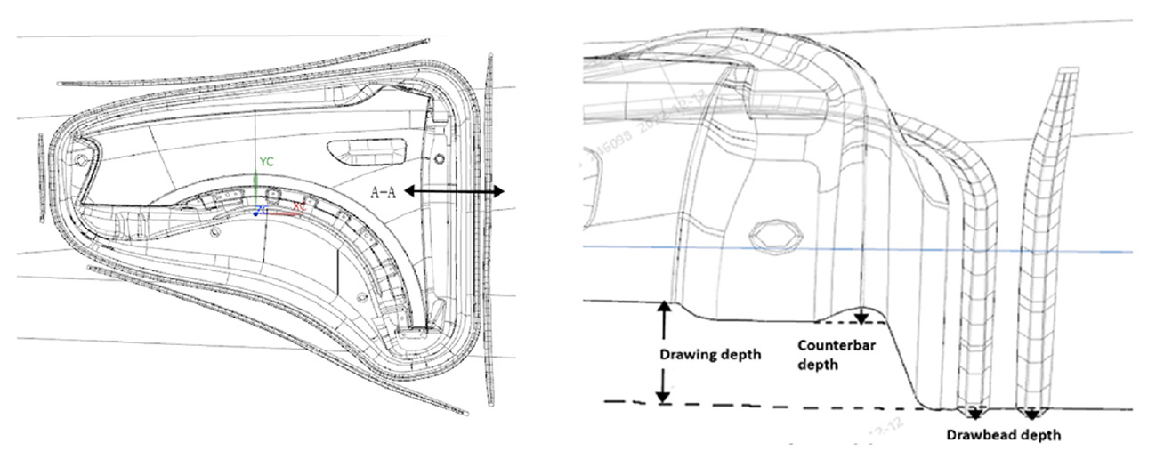
Fig. 10: Addendum of the fender process
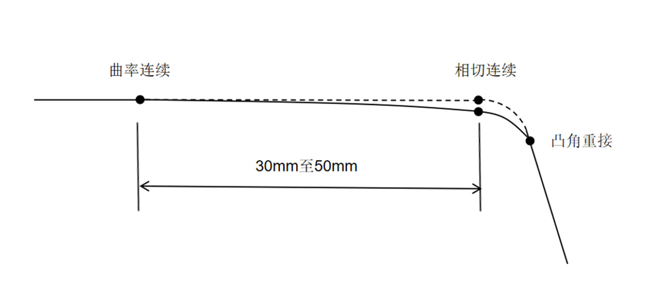
Fig. 11: Milling data compensation comparison
After compensation, curvature changes depend mainly on the original curvature direction of the Class-A surface. When the original curvature direction is downward, compensation reverses the curvature, as shown in Figures 12 and 13. When the original curvature direction is upward, compensation does not reverse the curvature but reduces its height, as shown in Figures 14 and 15.
At the junction between compensated and uncompensated regions, curvature changes remain continuous and gradual. Even when curvature direction is reversed, surface smoothness is maintained, and the curvature can still be considered acceptable.
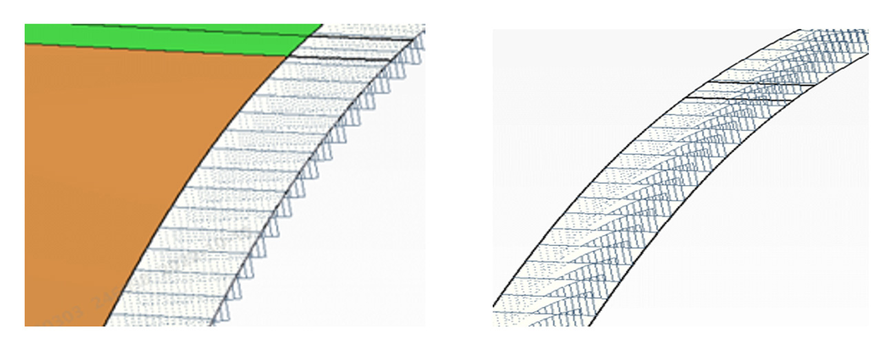
Fig. 12: (left) Downward curvature before compensation
Fig. 13: (right) Curvature reversal after compensation
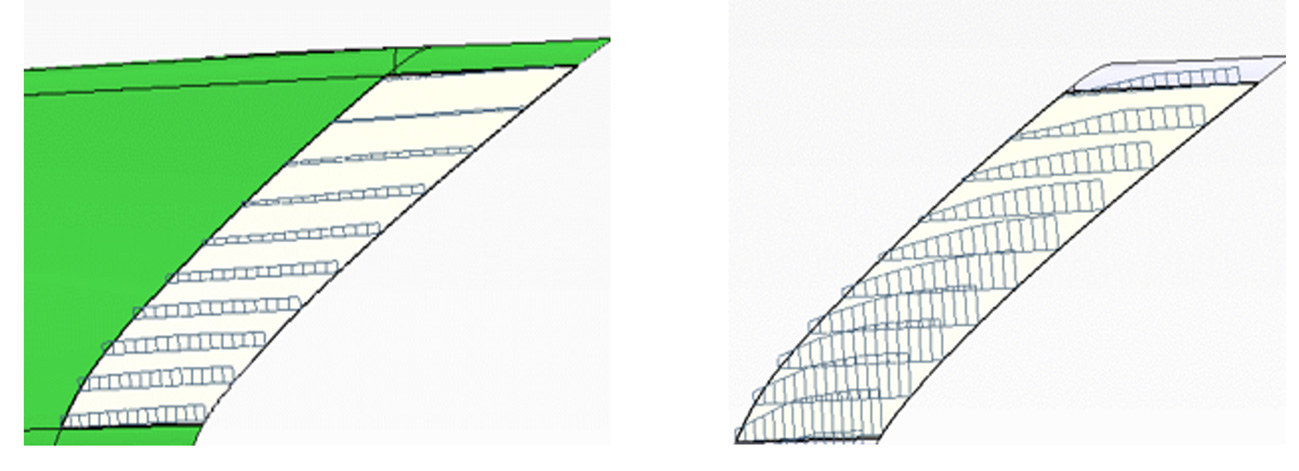
Fig. 14: (Left) Upward curvature before compensation
Fig. 15: (Right) Curvature without reversal after compensation
4 Validation
Theoretical analysis must be validated to confirm its accuracy. Based on the fender analysis, surface parameters did not meet standards, indicating a high risk of line break defects without early compensation. During milling data preparation, a 40 mm downward compensation of 0.1 mm was applied at the A-pillar area. Curvature continuity and zebra stripe smoothness were checked simultaneously. After confirmation, NC processing surfaces were replaced with compensated data across the full process.
The first produced part showed no obvious line break defect, and the oil stone scribing inspection result is shown in Figure 16.
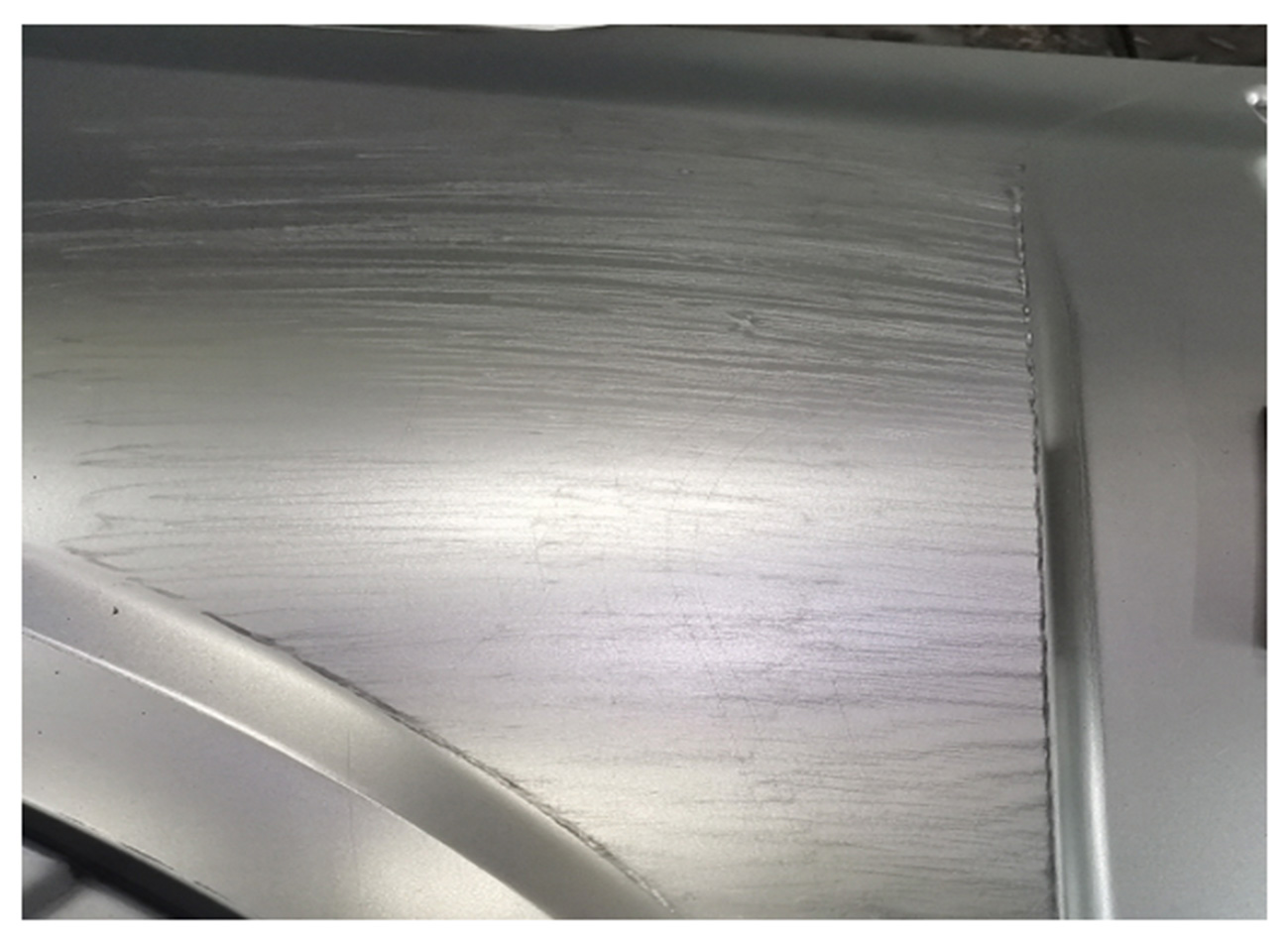
Fig. 16: Oilstone scribing inspection
To verify the robustness of this approach, four additional fender projects with similar parameter deficiencies were selected. The same compensation strategy was applied during NC data preparation, followed by die processing, assembly, and polishing. The first tryout parts from all four projects showed no obvious line break defects. This confirms that line break defects can be effectively optimized or eliminated through advance compensation of NC machining data based on early simulation results.
5 Conclusion
Line break defects in fenders can be identified at an early stage using AutoForm simulation. Key influencing parameters include minimum thinning, major strain, minor strain, minor stress, and surface quality. If any of these parameters fail to meet standards, line break defects are likely to occur.
The proposed solution consists of two steps. First, during process design, drawing depth should be increased and made more uniform in critical areas, along with deeper drawbeads. Second, if surface defects persist, NC machining data should be compensated as described in this study. This approach effectively reduces surface defects in early production stages.
On behalf of our FormignWorld.com readers, we’d like to thank Chen Lei
Chongqing SERES New Energy Vehicle Research Institute Co., Ltd.
Postal code: 401335


?")


