
In sheet metal forming, friction has always been one of the most influential and difficult variables to predict. Even with advanced simulation tools, many engineering teams still encounter a familiar problem: what works in simulation doesn’t always match what happens in tryout or production.
In many cases, the root cause is not the material model or the geometry, but how friction is described (Fig.1).
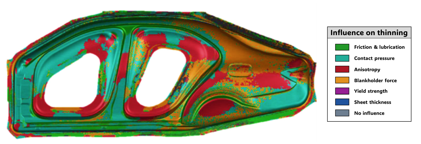
Figure 1. Friction dominates sheet thinning up to 70% for a uniside panel. Source: Journal of Physics
Traditional approaches often rely on simplified assumptions—typically, a constant coefficient of friction (commonly known as Coulomb friction) applied across the entire part. While this may be sufficient for less complex components, it quickly breaks down when dealing with modern automotive parts, where geometries are more intricate, materials are thinner, and process windows are tighter.
The reality is that the coefficient of friction (CoF) is not a constant value.
It evolves throughout the forming process, and one of the most important, yet often overlooked, drivers of that evolution is strain-induced surface roughening.
What is Strain-Induced Surface Roughening?
When sheet metal is stretched during forming, its internal structure changes. At a microscopic level, the grains within the material shift and reorient under plastic strain. This process alters not only the surface topography but also its roughness (Fig. 2).
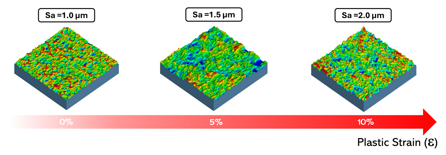
Figure 2. Surface topography changes and surface roughness increases with rising plastic strain ().
A simple way to visualize this is to imagine a perfectly flat landscape. As the material stretches, the surface begins to undulate, forming peaks and valleys, like hills emerging during an earthquake. As a result, the surface becomes rougher than before.
This phenomenon is known as surface roughening.
Historically, most friction models have focused on the opposite effect: surface flattening, in which contact pressure from die tools smooths the sheet surface, reducing the resulting CoF (Fig. 3). While surface flattening does occur during stamping, it is only part of the picture. In reality, both surface flattening and roughening occur simultaneously, and under certain conditions, roughening can even dominate.
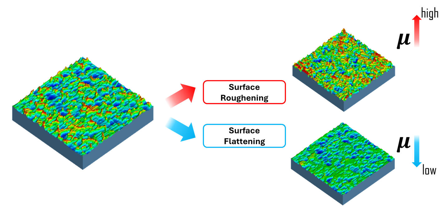
Figure 3. Evolution of sheet surface topography due to surface roughening (stretching) and surface flattening (tool contact pressure).
For instance, when the surface becomes rougher:
* Surface roughness increases
* Contact conditions change as more sharp asperities come in contact
* Lubrication behavior shifts, reducing the load-carrying capacity of lubricants
* As a result, the CoF increases
This means that areas of the part undergoing high strain (such as stretched regions under the drawbead) can experience significantly higher friction than predicted by traditional models (Fig. 4).
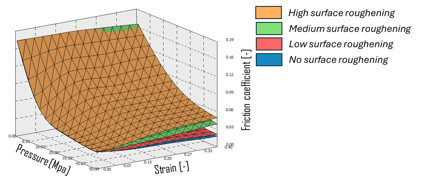
Figure 4. Friction coefficient as a function of pressure and strain, showing a decrease due to flattening and an increase due to roughening. Materials with high roughening behavior can lead to very high CoF, increasing the risk of splits.
The Customer Problem: When Simulation and Reality Diverge
For many stamping engineers, this gap shows up in a very practical way.
An automotive part that appears safe in simulation may fail in tryout. Or two seemingly identical parts produced using sheet material from different suppliers can behave completely differently (Fig. 5).
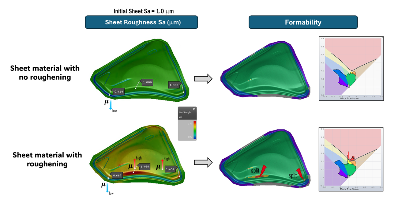
Figure 5. Effect of surface roughening on part formability. The same material grade from different suppliers can show different surface roughening behavior.
For example:
* Sheet from Supplier A shows splits
* The same part from Supplier B runs clean and “green”
From a simulation standpoint, this inconsistency is frustrating. From a production standpoint, it’s costly.
These issues are typically faced by:
* Forming engineers
* Tooling engineers
* Simulation specialists
And they often get stuck trying to answer the same question…
Why Doesn’t the Simulation Match Reality?
Without accounting for evolving friction conditions (particularly those driven by strain-induced roughening), simulation results can miss critical failure mechanisms.
The Old Way: Trial, Error, and Expensive Corrections
When simulation falls short, teams revert to what has traditionally worked: physical iteration.
This usually means:
* Running multiple tryout loops
* Adjusting press conditions
* Polishing or modifying tooling
* Reworking dies after production issues appear
This trial-and-error approach is time-consuming and expensive. Late-stage die modifications can significantly increase development costs and delay production timelines. Even worse, these corrections are often reactive rather than predictive.
A Step Closer to Reality: Accurate Friction Prediction
To address this challenge, AutoForm, through its TriboForm solution, has introduced a new capability that incorporates the effects of strain-induced surface roughening into friction calculations.
Instead of treating friction as a fixed input, engineers can now account for how it evolves during forming. In practical terms, this allows simulations to better reflect real shop-floor conditions, not only during tryout, but throughout production as well.
Curious about how TriboForm friction works? Check out this webinar, which explains surface flattening in detail for automotive applications and demonstrates how TriboForm friction improved correlation issues at Volvo Cars and Ford Otosan.
Why This Matters Now
As vehicle designs become more complex and lightweighting continues to drive material selection, forming processes are operating closer to their limits than ever before.
Under these conditions, small inaccuracies in friction modelling can have a significant impact.
What was once considered “good enough” is no longer sufficient.
Strain-induced surface roughening reflects a broader shift in simulation technology: moving beyond simplified assumptions toward physics-driven, evolving models that more accurately represent real manufacturing conditions.
Explore TriboForm today and get in touch with the TriboForm team.


?")


