
Ford Otosan Talks Customer Satisfaction for Keeping Within Tolerance
In this blog post Stamping Process Engineer Fatih Onhon from the Tool & Die Department at Ford Otosan in Turkey reveals a case study for the springback compensation of a door opening panel (DOP) for a cargo truck. He reveals some of Ford’s operating norms for springback minimization and publishes some astounding results!
Springback is one of the most important issues in my work as a Stamping Process Engineer. As the one and only cause of form deviations for a stamped part it is precisely where cost is incurred in terms of lost money and time. Most will agree any other issue is slightly easier to solve. With increasing use of materials such HSS and AHSS, which produce more elastic return, virtual engineering has become increasingly crucial for its management.
“It’s a must if you want to reduce time to delivery of a die line while keeping the costs under control and achieving high final quality” said Fatih.
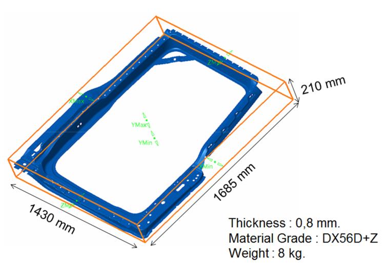
Fig. 1: Dimensions of Door Opening Panel (DOP)
We spend a lot of time reading research outcomes to find cutting edge methods that will give us an advantage. But, once you depart the academic world and enter the industrial then things change as there are other demands. The main goal is customer satisfaction. For the customer buying the part the main factor is the Percentage of Inspection points Satisfaction Tolerances – PIST. The minimum PIST value required for mating surfaces, which tolerance is ±0.5mm (but sometimes even ±0.25mm) is usually 90%. Yet this value is about to change to reach 95% quite soon! Dimensional accuracy is becoming more and more stringent.
With this in mind, the expectation is for engineering to master springback and leave little room for expensive mistakes!
Compensation cannot be viewed as the only way to address dimensional issues (it is not always that simple) but other countermeasures have to be put in place before actually getting to step of tool compensation. Springback minimization is an important aspect of the entire process: to reduce the magnitude of the deviation of the sheet from the nominal geometry is important as well as the stability (robustness) of the behavior of the sheet (consistency of the springback direction when process parameters may slightly differ from nominal).
Expedients to reduce the magnitude and ensure compensatibility can either come from tool geometry (gainers, radii reductions) as well as from process parameters (tool time entry – tool impact). When getting to compensation, the way we measure springback is fundamental and therefore the clamping concept becomes really important.
There is no need to remark on the importance of having a FEA simulation software to evaluate different options and select the most effective countermeasure to achieve the PIST”
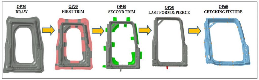
Fig. 2: Production operations of DOP (4 operations + 1 measurement fixture)
As shown above, the production of a DOP requires four stamping operations in the press line. In the simulation software the, measurement of the final part on a checking fixture is also set as an operation. The DOP part is a double unattached type which means we stamp right and left door on the same die line starting from two different blanks. Because of the dimensions of the parts we can definitely say that the die is one of the biggest in size you may come across within the sheet metal stamping industry.
We had prerequisites to be compliant with for the validity of springback results, as well as formability which of course must not show risk of splits, wrinkles etc. and the thinning distribution had to be within a given tolerance limit. In order to ensure that there will not be geometrical wrinkling on the part surface, wrinkling behavior had to be checked at 10 mm, 5 mm and 1 mm before reaching the bottom of the stroke.
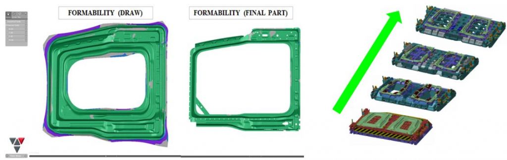
Fig. 3: Left, formability output of draw and final part form. Right, die-set design.
The formability results of the process simulation reached a “green result” meaning the part would be free of splits and heavy wrinkling conditions ensuring at the same time the desired stretch amount of the material. Below are the input parameters of the full process simulation.
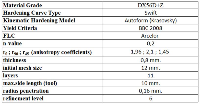
Fig: 4. Input parameters of full process simulation of DOP
Since slight changes in input parameters can make big difference, and because of unavoidable variation occurring in serial production, we ran the robustness analysis.
At Ford this process is becoming more important from a springback point of view. The figure below shows the result of noise variation level and the Cpk value as indicators. According to our standard, if Cpk >= 1,33 then the process is accepted because the level of stability (robustness) is reached.
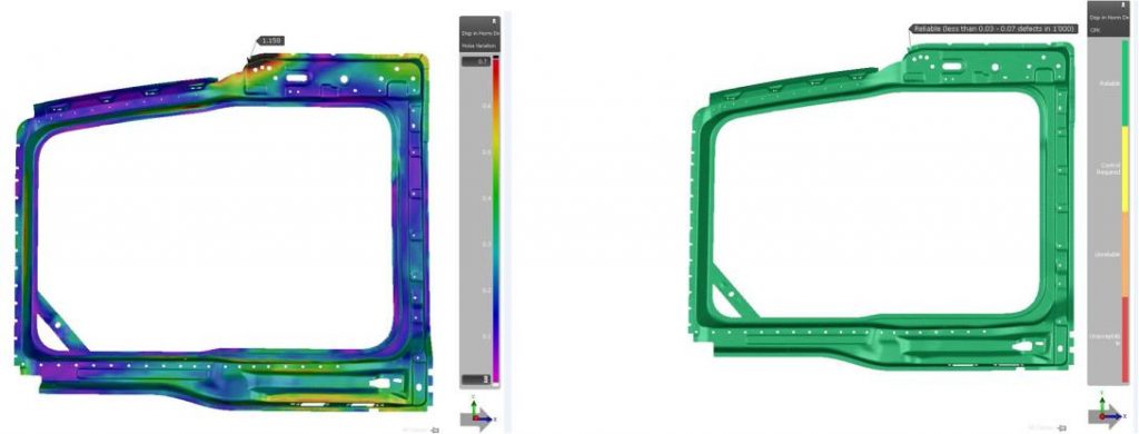
Fig: 5. Left, noise variation of DOP. Right, Cpk of DOP
Getting to springback, since the compensation of the outer panel puts its quality (style) at risk, only the compensation on the inner panel is preferred. Like the outer part, stretching is also effective, but the PDPD (Process Driven Product Design) is a more useful countermeasure used to decrease springback here. By adding extra geometries, such as ribs, swages etc. to the part CAD data you can “easily” keep the springback under control.
For compensating the DOP our method was to compare the springback measured in OP60 (checking fixture) and the one in OP40 to fix the effect of secondary forming on the springback as seen in the below figure. If there is no major effect of secondary forming than we can compensate D20 tool according to the OP60 result. The draw die surface will be morphed as shown below (1st step). Any springback in OP50 can be compensated in the OP50 die. Of course, compensation strategy must be validated through a full cycle simulation where also the fitting of sheet on the trimming dies (pad-post) is also checked (avoid panel restrike and apply unwanted plastic modifications). But if secondary forming has a major effect on the overall springback than compensation gets complex.
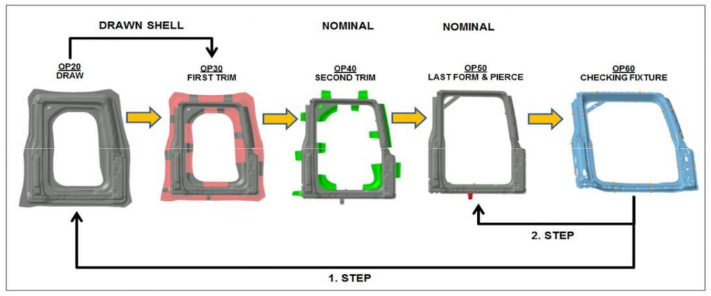
Fig: 6. Compensation steps of DOP
Conclusion
As result of the project, the figure below shows three PIST values. The figure on the left shows the simulated springback value when no tool compensation is performed. As you can see the PIST value is 63% and it is not acceptable (minimum requirement is PIST=90%).
Once the tool compensation is performed we obtain a 99% of PIST value: the minimum required value is reached (see figure in the middle). Virtual PIST values are the values obtained from AutoForm’s FEA software.
On the right side of the figure below, you see the actual PIST value obtained of the real stamped part. For mating surfaces it reached 92% and for non-mating surfaces 100%. A really impressive result has been reached!
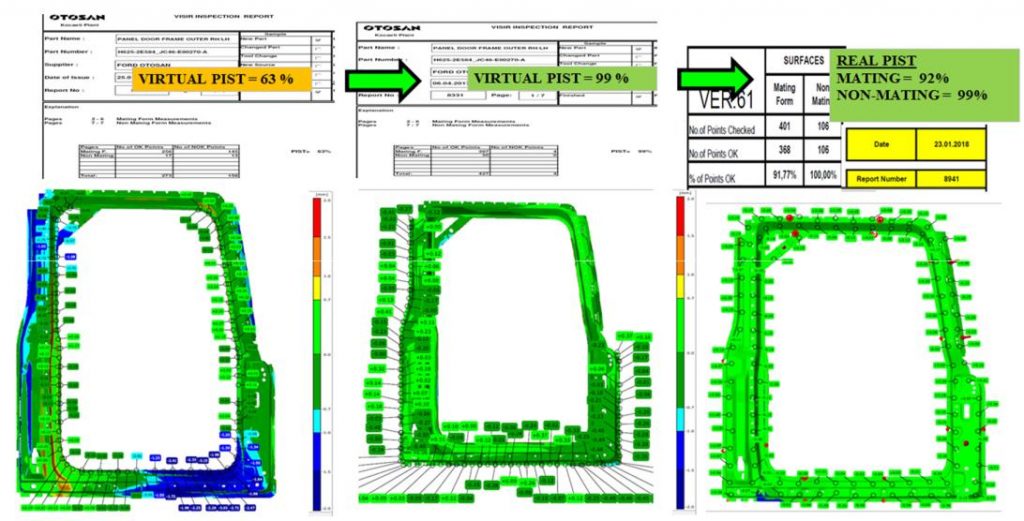
Fig: 7. Comparison of virtual and real PIST values of DOP
Note: source paper – “Evaluation of all Springback Aspects through a Success Story on Ford Cargo Truck Door Opening Part: MS-10-14” IDDRG. With Permission from Fatih Onhon.
New readers, don’t forget to sign up to our blog! We’ll never send you marketing emails, only a once per month highlight of top recent posts!


?")

