
“What do we need to change to make it work?” This is most likely the first question that pops into your mind after the first attempt to hem an inner and outer door panel (door sub-assembly) fails.
This kind of question is common in the hemming tool shop at the beginning of a tryout; people are used to not getting it right on the first attempt. But after days (and sometimes months) of the same ongoing trial, the question slowly becomes, “Whose fault is it?” When you begin to feel that no matter what you do, the assembly will never be completed within tolerance, this question increasingly takes over.
Here at AutoForm, whenever we receive a call from tool shops inquiring whether there’s a solution to their issue, we never ask about who or when (you never find someone still standing with the smoking gun in their hand, anyway). Instead, we focus on why the issue occurred in the first place. And how to fix it.
To achieve that, we need to dig deeply into the root cause, because only then can we gain a comprehensive analysis that will guide us to a systematic solution.
If we look at the stamping and hemming processes (see Fig. 1) from engineering to tool tryout, we usually see that there is no data exchange whatsoever among the stamping process designers themselves (the inner and outer stamping processes proceed simultaneously without data exchange) or between them and the hemming process designers.
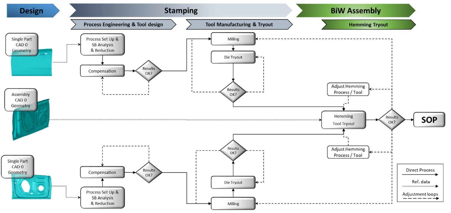
Fig. 1: (Click to enlarge) From Stamping to Assembly
– Today’s Typical Workflow
Stamping process designers consider the so-called “CAD 0”-geometry as reference only (GD&T define tolerances on it, e.g. ±0.5 mm), not taking into account that the same part will undergo another forming operation (hemming) — the result of which is anything but guaranteed.
Hemming tools are also built based on CAD 0 geometry of the assembly, generally without any consideration of the physics of the panels (gravity, residual stresses, etc.).
In our latest webinar, “Why perfect stampings do not produce perfect assemblies,” I explored this aspect of the process. Through a real-life example, we showed how considering hemming results upfront during the stamping process engineering, and actually driving it according to hemming process outcomes, can minimize the risk of expensive and time-consuming re-engineering processes.
When AutoForm got involved in the project, all stamping and hemming tools for the door assembly shown in Fig. 2 had already been built.
After many weeks in tryout, the door sub-assembly still wasn’t within tolerance.

Fig. 2: Door sub-assembly (object of the project)
The probability that the solution could only be found by modifying the inner and/or outer panel increased after each hemming tool trial. It’s worth noting that we had already ruled out the easiest conclusion, which everyone checks out first in these cases: both panels were within tolerance; stamping was delivering “green” parts.
Probability became reality once a full virtual analysis of the real hemming process was complete. The hemming tools were replicated as closely as possible in the virtual environment, where the effect of process parameters on the result could be checked quickly and thoroughly. The area percentage of the sub-assembly within tolerance was lower than the target, no matter which parameter values and/or shape of the tools were used. The evaluation from the quality department was decisive: rejected!
There were now questions to be answered. To fix the issue, should both parts be re-engineered with different tolerances, etc.? Could a die line be saved (and a couple hundred thousand Euros with it)? And if that was the case, which die line?
To answer all these questions, we started to analyze both stamping processes, integrating the hemming operation from the very beginning to understand what the assembled parts would look like.
Figure 3 shows the workflow we put in place, essentially replacing the current typical workflow (see Fig. 1) — checking the hemming results from the first process feasibility studies and actually making decisions based on the outcomes of the hemming process simulation.
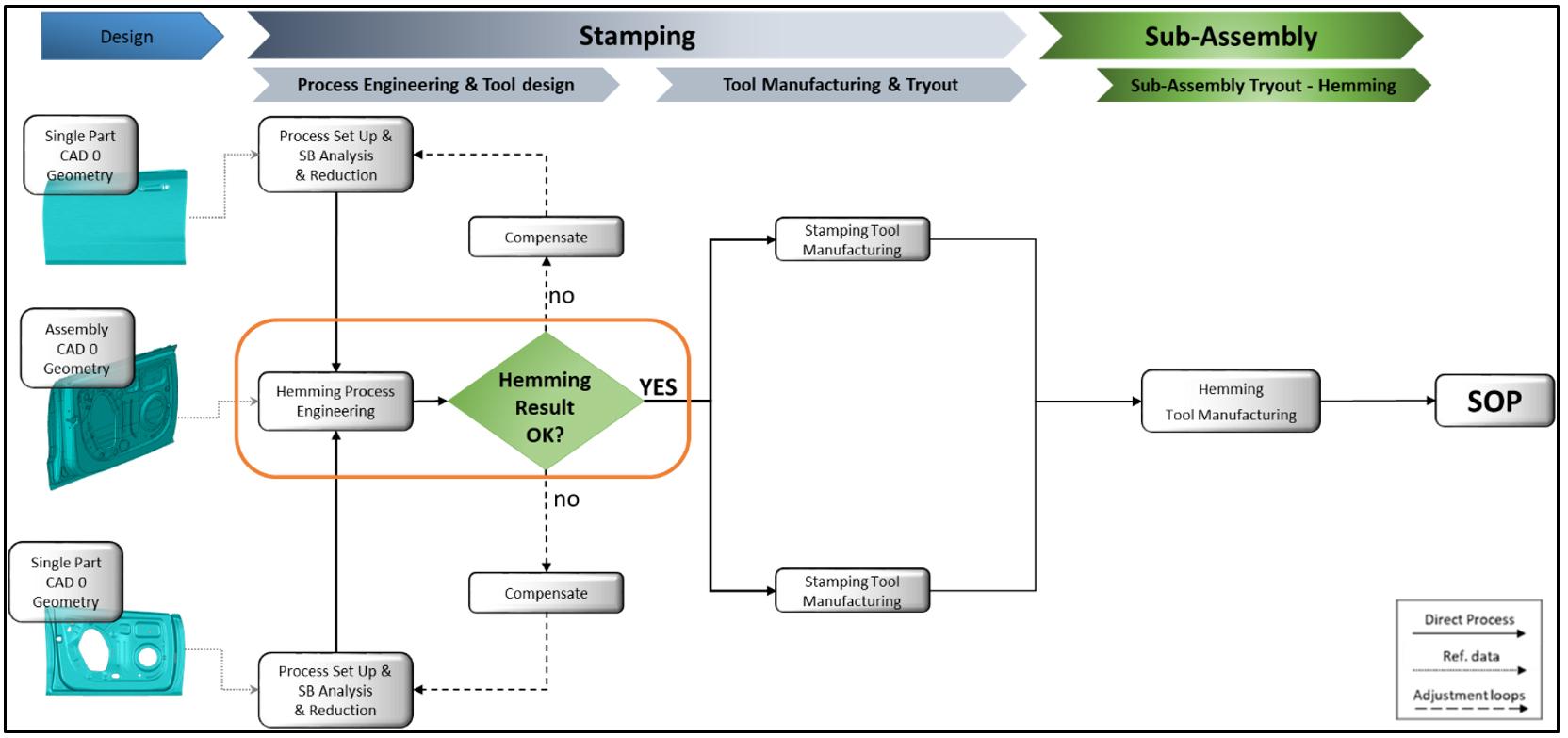
Fig. 3: (Click to enlarge) Stamping process driven by hemming results
Only after the hemming process was simulated and results were evaluated could we make the decision to compensate either both tools or only one of them. In other words, what we were trying to accomplish was the definition of a trend of behavior of the assembly based on the behavior of the single parts.
The first virtual hemming trial was performed with panels produced by “non-compensated” tools: by comparing the springback of single parts with the springback of the sub-assembly, we tried to understand whether there was a dominant panel or not.
As you can see in Fig. 4, the springback results of the assembled door were more consistent with the results of the inner panel springback (the green area shows the part within ±0.5 mm tolerance).
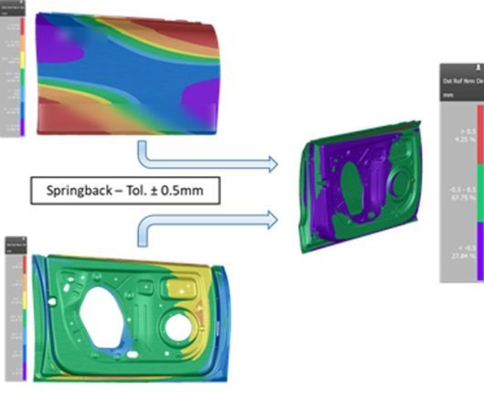
Fig. 4: Single-part springback vs sub-assembly springback
Checking the results of the sub-assembly, we see that 67% of the total area was within tolerance: it seems that the inner panel was pulling the outer within tolerance! This was already an important indication that needed a more in-depth analysis.
The minor influence of the outer panel on the final hemming result was confirmed when we compensated only the outer panel tools: the panel was still within tolerance (as occurred in reality). We hemmed the outer panel produced by compensated tools with the inner as shown in Fig. 4 (no compensation performed) and the total area of the assembly that was within tolerance did not change significantly (see Fig. 5).
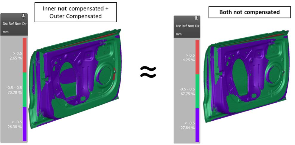
Fig. 5: Negligible effect of the outer panel compensation
Did we waste our time?
Good question, isn’t it? Truth be told, we spent a significant amount of time looking for the best compesation strategy to bring the outer panel within tolerance (which is what any engineer does, as required by stamping targets), without bringing tangible benefit to the final sub-assembly. Apparently, yes, we wasted our time…
This is an interesting outcome of the analysis. The stampers could have saved time and money by avoiding over-engineering of the process (and, likely, many loops in tool tryout to meet such tight tolerances).
The good news is — a couple hundred thousand Euros can be saved!
Getting back to the project, based on the previous and additional analyses where only the inner panel was compensated, we decided to modify only the inner panel stamping process and to keep the outer panel die line unchanged.
Time to define a new reference target!
So, let’s compensate the inner panel only. Fine. But the question is: based on which springback measurements should we compensate the tools?
We decided to measure the springback of the real assembled inner panel (scan data vs. assembly reference geometry) and use the deviation from the reference to compensate the tools.
Before beginning to re-mill the tools in reality (and trash what was already built), the idea needed to be virtually validated.
The stamping process of the inner panel was simulated one last time and the panel placed in the virtual hemming tools with the real (scanned) outer panel. Remember, we did not change the tools of the outer panel so we had to make sure that the “old” outer panel was going to work with the “new” inner panel.
The results of the virtual process validation is shown in Fig. 6. We checked the portions of the part within ±0.5 mm and ±0.7 mm using the CAD 0 geometry of the assembly as reference.
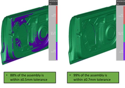
Fig. 6: Process validation results
Done!
According to these results, we made the decision to recut only the inner panel die line and keep the existing outer panel die line.
Design for production
This is another concept to keep firmly in mind. The final goal of all activities, from engineering to tool manufacturing, is the mass production of parts and sub-assemblies. Our ultimate objective is to build the entire car body, and we want to make it with the best cost/quality ratio. In other words, we want to be efficient!
Being efficient in production is not just a matter of reacting as quickly and effectively as possible when issues occur (because they do occur). Efficiency must be designed and maintained during tool manufacturing (tryout). In other words, efficiency must be ensured along the entire process chain and in all different departments and tool shops. This is the only way to truly produce efficiently!
With these principles in mind, we checked the stability or, more technically speaking, the capability of the stamping processes considering unwanted and uncontrollable parameter variations. We checked the stability before and after compensation, the results of which are shown in Figure 7.
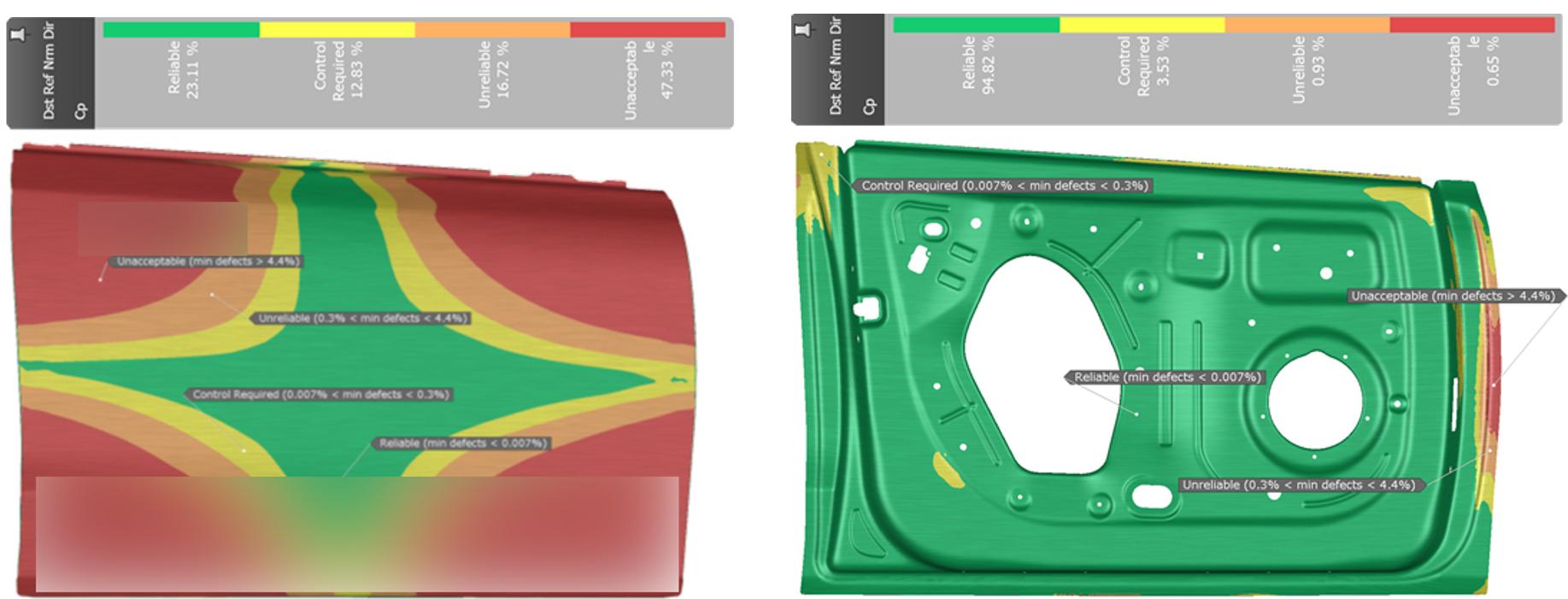
Fig. 7: (Click to enlarge) Before and after compensation.
The two processes each have quite a different capability (Cp). The process to produce the outer panel is not stable enough, as shown by the amount of “red” area on the panel. On the contrary, the production process of the inner panel is quite stable.
What does this mean in reality? It means that we do not know the process capability of the assembly production process. We are unable to predict how many parts and therefore sub-assemblies will be “green” and how many will be out of spec when variability of certain parameters (material, lube, etc.) occurs.
In our project, owing to the low influence of the outer panel on the final assembly outcome, the customer decided to keep the tools the way they were built (the analysis was not actually performed during process engineering, by the way) — with the hope that the higher stability of the inner panel would be dominant during mass production.
Lessons learned
The entire stamping and assembly process that’s been in place for decades has reached its potential and if we really want to be more efficient in production, stay competitive and be profitable we have to embrace process digitalization principles and make changes to the process. Digital transformation cannot be applied spot-like (here and there inconsistently) but it has to be applied along the entire process chain, from engineering to production.
What does this mean for the process in place? Should we throw what we learned in the past decade in a trash-bin?
Of course not – but for sure it will have to change. Data must be shared consistently and in a meaningful way across departments and suppliers as they become available so that who comes later in the process can start his own evaluation as soon as possible and actually drive and optimize the whole process altogether.
Is this easy to do?
No, not at all. But, as I used to say, if you never start you’ll never get it done and never move forward! Technology is there and moving fast, we only need to hop onboard!


?")


