
Hemming is the major technique used to join inner and outer panels in automotive closure parts. A high quality and robust hemming process ensures stability of the entire car body, providing improved crash safety for its passengers. BAIC Motor frequently faced issues when ramping up hemming production. To mitigate these problems, the company intends to optimize their product design and engineering workflow together with AutoForm.
The hemming width is among the critical process parameters affecting the quality of any hemming operation. Correctly defining the hemming width in the part design phase not only reduces hemming tryout loops, but also saves time and expenses involved in modifying the outer panel cutting dies at a later stage.
Generally, the outer panel is drawn, trimmed and flanged prior to the hemming process. In the process design stage, the flange height, flange angle and overbend amount of the outer are all defined (Fig.1). The flange height of the outer is essentially expanded according to the hemming width, reflecting whether the sheet panel will wrinkle or split when the sheet is hemmed. To safeguard the hemming quality, the flange angle of the outer should be controlled within 90-105 degrees. The flange angle requirements can be relaxed when applying the roll-hemming technique but as a general rule, the larger the flange angle, the more rounds required. The overbend amount is a compensation method used to offset the generated roll-in when hemming, determining the accuracy of the gap clearance with another outer.
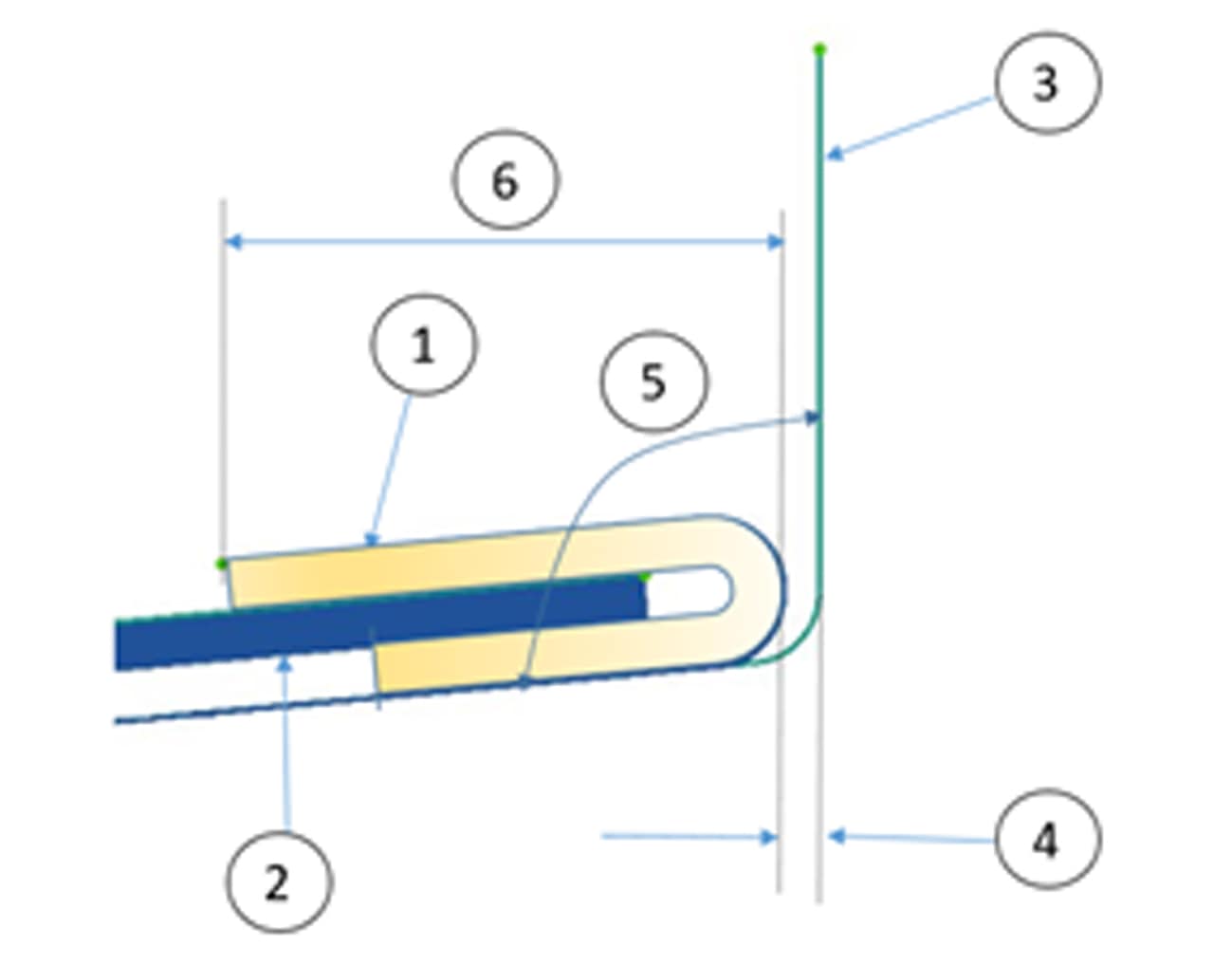
Fig.1. 1. Hemmed part; 2. Inner part; 3. Flange part; 4. Overbend; 5. Flange angle; 6. Hemming width
At present, designers rely on individual experience when defining the hemming width of the outer panel. However, as outer panels face increasing diversification and limitations, this approach has been called into question. Only a slight difference in the flange height can cause wrinkles or splits. When this happens, it’s necessary to go back to the trim die of the outer panel to adjust the trim line; some cases even require modification to the outer panel modeling, resulting in significant rework and cost.
AutoForm software allows the designer to analyze the flange height according to the value defined in the early part design stage. The suitability of the flange height can then be determined through the wrinkle and split evaluation.
BAIC Motor regularly faces challenges in the hemming tryout of their hood outer production. To address these issues, BAIC teamed up with AutoForm China to investigate a sample hood assembly. For this case study, the hemming type applied to the hood is roll-hemming. The initial hemming width of the flat straight area is mostly set to 8mm, the convex circular area is 6mm, and the sharp angle position is 4mm. We can unfold the hemmed geometry to the flanging state rapidly using the Unfold function in AutoForm (as shown in Fig.2), and perform the hemming process simulation according to the hemming plan. The initial AutoForm analysis predicts wrinkles occurring in three areas of the hood (as shown in Fig.3).
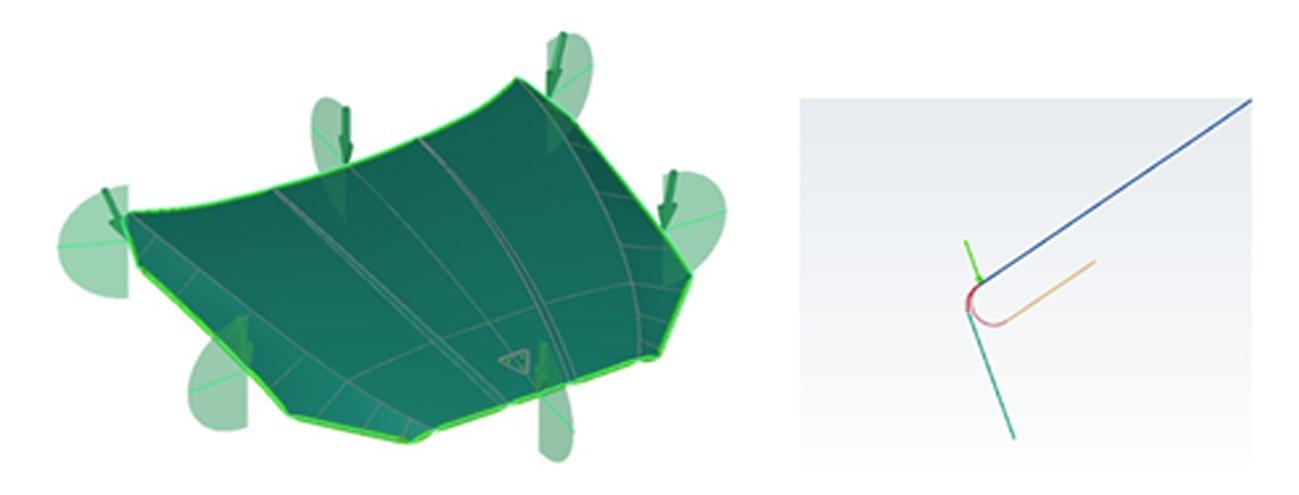
Fig.2. Unfold function
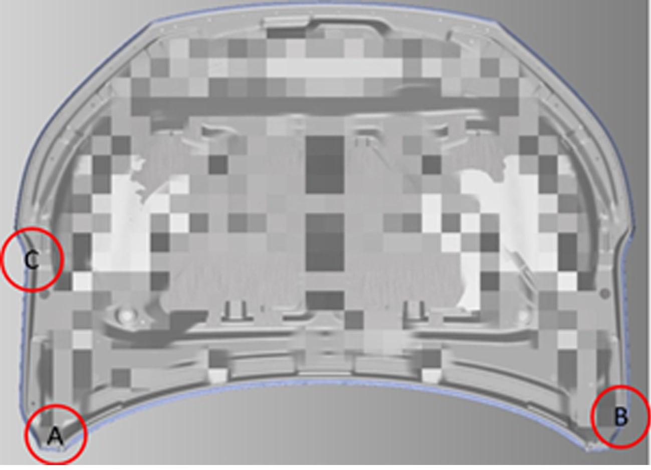
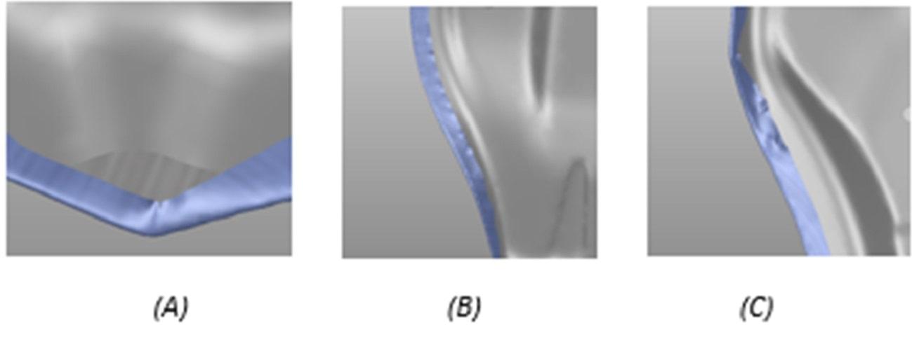
Fig.3. Initial wrinkle
During the hemming process, the analysis predicts thinning to occur on the radii. According to the principle of constant volume, thinning in the thickness direction will cause elongation in the bending direction — variations in thinning cause variations in elongation. Without simulation technology, it’s practically impossible to determine the correct hemming width in these regions (as shown in Fig.4).
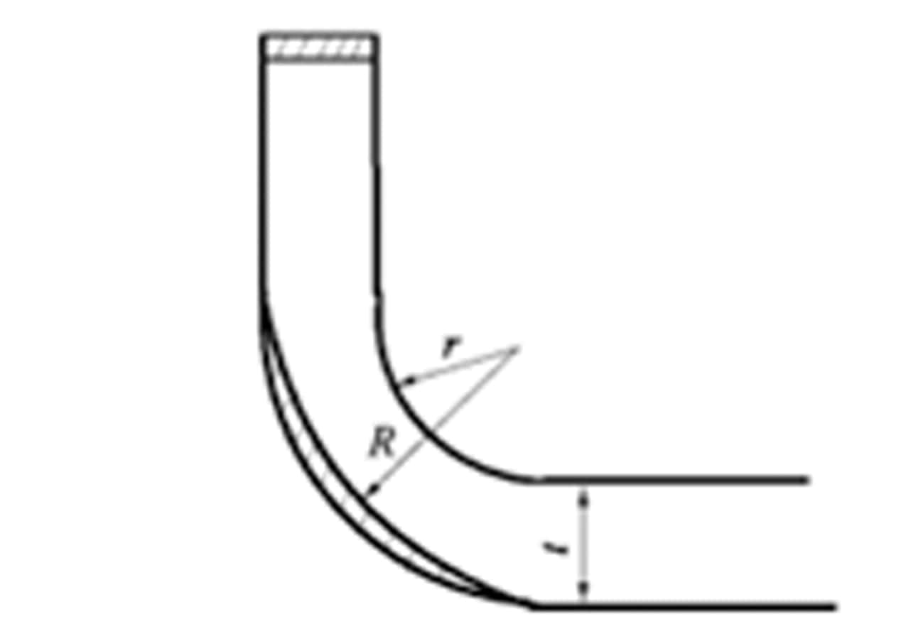
Fig.4. Sheet elongation due to thinning in bending area
Using AutoForm software, we can observe the details of the wrinkling, determining when and where it occurs. Even more importantly, we can easily modify the hemming width and recheck the formability until a good result is achieved. In some cases, we can resolve wrinkles by modifying the hemming width, while other cases require removal of the hemming — like the sharp corner A shown in Fig.5 below.
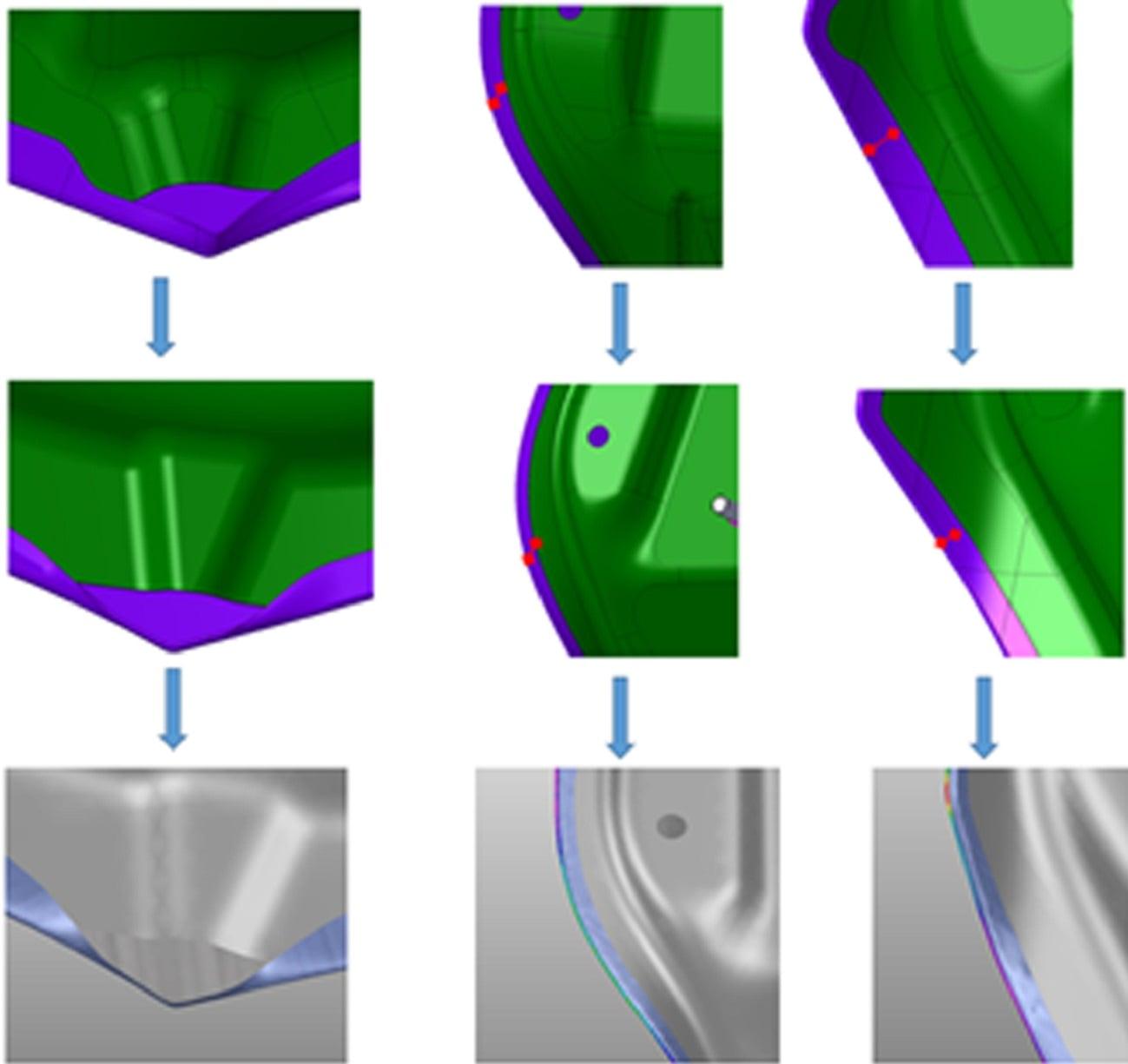
(A) (B) (C)
Fig.5. Modify hemming width
In area B, we see that a slight hemming width adjustment causes significant alterations to the wrinkles, as shown in Fig.6.
6mm 5mm
Fig.6. Wrinkle comparison with different hemming width
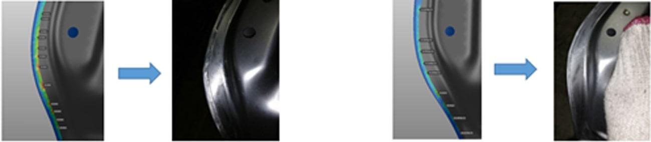
Finally, in the physical tryout stage, these three areas are basically consistent with the simulation results, as shown in Fig.7. The simulation of the given hemming width not only meets the design requirements, but also reduces tryout loops.
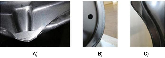
Fig.7. Real panel
BAIC Motor typically takes minimum three tryout loops to determine the ideal hemming path for a robust hemming production to deliver high-quality closures. Each loop takes around one month for several departments and suppliers to perform the necessary reworking. The trimming die requires at least one time adjustment. To that end, applying AutoForm’s “quick hemming” simulation for feasibility evaluation and hemming width definition in the early part design phase and “advanced hemming” in the engineering phase has the potential to achieve the desired results in just one tryout loop, saving several months of work and significant costs per hemming group.
Since completing this case study, BAIC Motor has established hemming simulation using AutoForm software as their standard process. This enables them to set their own roll-hemming standards rather than depending on the advice of their suppliers.
Zhang Qiang, BAIC Beijing Manufacturing Centre ME Department


?")

