
Introduction
Most of the time, we think of things in reference to the extremes so we can better understand them. It is like reflecting on the statement, “The worst that could happen is…” We try to protect against the conditions that would cause the biggest problem or the least favorable outcome. It’s not too painful to learn you could have had another 5 mm of blank savings in your process if production rates are high. It would be far worse to have a process that saved $0.20 per blank but with scrap rates consistently over 30% and requiring constant die maintenance.
The latter is a case we would always want to prevent…right? But each person has a different perspective which drives different behavior. “You can’t worry about blank cost until you can actually make the part.” “If cost is not engineered at the beginning, you can’t easily improve the system at the end.” These are two common opposing approaches. I think the reason for different philosophies is due to engineering time. It becomes too many studies and too much understanding of multiple ranges, requiring far more time than designing something in one limited way. Most importantly for this article, we can start to include more in our initial analysis while still addressing a focused topic, but in a more detailed way. So this question arises: Is it the responsibility of the Process Designer to continually meet both formability and cost targets equally? What about production robustness?
In addition to aggressive quality and cost targets, the schedule must be respected. Generally, the project schedule is king, and this affects team decisions that otherwise would not need to be considered. Trade-offs will happen and actions taken that are not ideal simply because time was not available. There is generally a “cost” associated with these decisions that are heavily influenced by a looming deadline. What if there was a design method or a system of tools that could keep the design maturation phase ahead of schedule while including more of the above mentioned quality and cost goals in the early engineering process? What would that be worth to you?
I find that it is best to break big problems into small tasks, use the correct tools for those tasks, and then move on to larger tasks. So what does this have to do with the amazing design process I mentioned above? Well, it is the foundation required for that system to be possible. Our philosophy and awareness about what is actually available, and our willingness to pursue a new direction, have everything to do with this “system” of tools. Otherwise, there would be no progress. Having said this, I am not convinced that a “perfect” system exists. But I do think that the necessary pieces and parts are mostly available today. There will always be room for innovation and improvements but we are far more capable today due to advancements in the available software solutions.
To explain one small task and the dedicated tool to deal with it, I propose the following situation, which many of you may be familiar with. I will use this example as a starting point for discussion. Please feel free to comment about different steps that you would take if faced with the same situation.
The Story
I am a Process Designer for a tool shop and I have almost finalized a draw concept design. I must follow the planned process, but certain decisions must still be made for the specific details of my design. Three main considerations are: surface quality, blank size, and formability robustness. The current results for one region of my design can be observed in the images below. Two main problems exist: firstly, the surface stretch is very low in the Class A region; secondly, there is a crack concern inside the rear door wall.
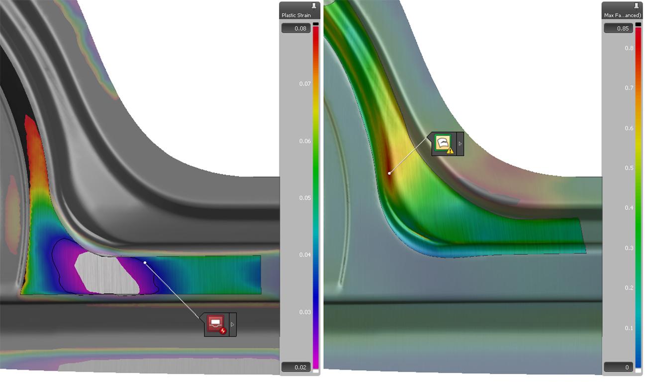
In these images, a few remaining problems need to be fixed. But have all the right questions been asked and investigated? Should I only focus on those problem regions at the bottom of the door openings? As the Process Designer, Development Engineer, or Formability Engineer, I must make a decision quickly to allow for any design maturation loops. The schedule is exactly on pace to finish just in time. Do I really have the time to investigate optimizing this design in addition to fixing the visible problems?
For discussion, I will initially focus my attention on the overdraw shape in the rear door. My idea is to modify the preform shape to allow the draw to be formed, and also balance the reforming amount to achieve the formability required for the full process. At the same time, I may be able to confirm that the blank is minimized and draw beads are in the correct position and designed to add more stretch in the Class A area. Below are some of the details of the design parameters I explored. These were carried out by automatic geometry modification and bead design adjustments. All these parameters are variable to determine the best combination. The rotation angle for the draw shape is of particular interest. In this case, I used a morphing capability to quickly modify the geometry. This many revisions are simply not feasible to complete and evaluate manually. Furthermore, understanding what combination of the variables produce a better result is not always intuitive.
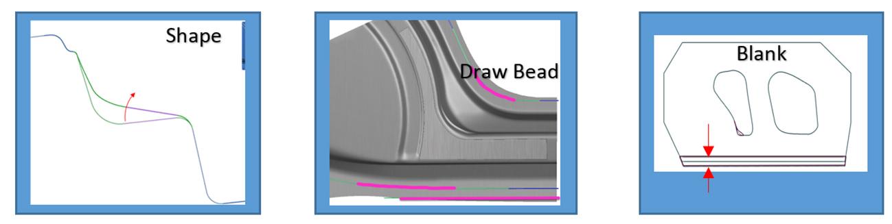
Geometry and Process Parameters for Design Variation
The outcome from our total group of simulations now allows us to confirm if our design parameters are influential to our target and that we can achieve a potentially robust process. In the follow images, we can see that the Class A surface stretch is more uniform and has increased substantially, while also avoiding the crack concern on the wall. In addition, the draw-in amount has been limited to a minimum value, allowing the final blank size to be optimized. It is true that some portions of this modification may still need some small adjustments. However, the general idea for modification has been proven to be valid and within reach for this specific process. The deform potential in the draw operation should be evaluated further, but this may involve other geometry parameters and process parameters not yet included in the design study. In any case, I have proven one idea has substantial potential, without creating roughly 100 versions of the simulation manually.
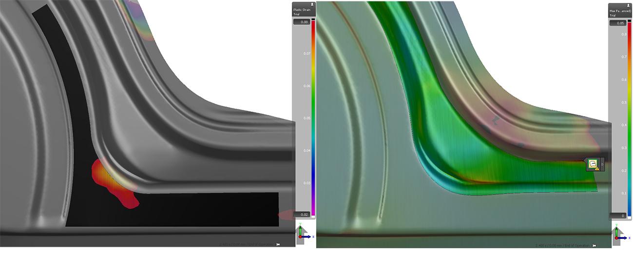
Draw Results – After Automatic Resolution of Parameter Values
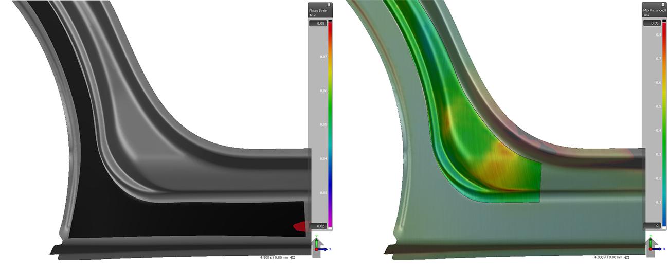
Reform/Trim Results – After Automatic Resolution of Parameter Values
Questions
- Do you already perform this type of automatic countermeasure analysis?
- If you do something similar, what software or method do you use to carry out your investigations?
Customers can review some helpful resources at the AutoForm Service Center website. For a different example on how to use other morph features, see one of our past related articles.


?")

