
Part Three: Needed or Not? Computing Flow Conditions Inside Cooling Channels.
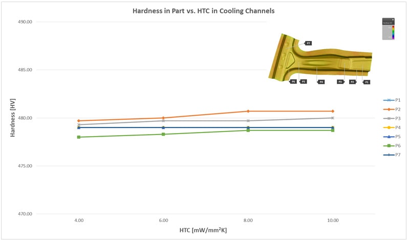
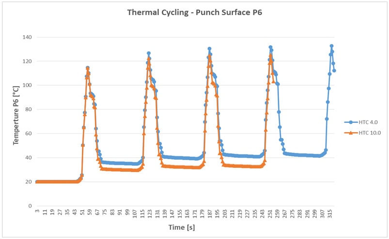
The impact of the position of the cooling channels embedded in the tool on final part quality has been the focus in past blog posts. In our previous post, addressing the necessities of modelling of local flow rates, pressure distributions, and thus finally the Heat Transfer Coefficient, Michael Düring, Product Manager at AutoForm mentions: ‘We found that in computing the flow conditions the impact was so negligible, and its effect was so slight in the end, that compared to working without it you would come to the same conclusion; that this is something which can safely be disregarded.’ Here in part three of this series we publish the actual study that supports that bold claim. This post is based on a paper titled ‘Impact of Flow Conditions in Cooling Channels on Thermal Cycling’ 2017, by Kannan Kidambi, Thomas Brenne and Michael Düring. The actual paper is available for download at the end of this post. The authors were able to show that even though an intentionally bad distribution of cooling channels in the tool bodies can lead to a pronounced inhomogeneity of the temperature field on the tool surface under regular process conditions (commonly called ‘hotspots’), such kind of inhomogeneity has a very limited influence on the quality of the final part. This is valid in particular for the resulting hardness. It seems that the order of heat conduction in the tool and the sheet itself, combined with damping effects of the heat transfer at the contact interfaces dominate the thermal system. While the authors of the study express their opinion that there is almost no influence of the flow conditions in the cooling channels on final part quality, others consider flow condition control as a vital prerequisite to achieving high quality parts. The latter consider that extensive CFD-studies towards accurate prediction of tool surface temperature distribution is crucial to do a dead-on prediction of final part quality outcomes from forming simulation. This is naturally linked to remarkable additional efforts spent in terms of installing equipment, modeling and computation. Variation of temperature distribution in a quenched part Exemplarily, a real tool geometry for a B-pillar has been converted into a model in AutoForm. The process itself was computed using AutoForm-ThermoSolverplus. All measures are taken from the same model configuration and controls settings. Subsequently, the HTC representing the interface between cooling media and cooling channel boundary has been varied representing modified flow conditions. Values between 4 and 10 mW/mm2K have been assumed. These values lead to remarkable differences in terms of tool surface temperatures. The impact on the temperatures in the sheet after quenching is far more moderate: at the end of the quenching stage, the range of predicted temperatures at any of the observed points on the sheet, over the applied HTC range of 4 to 10 mW/mm2K, are observed to be within a range of around 5% – as shown in Figure 1. This indicates that the evolution of the cyclic (steady state) temperature fields is also not affected in a way that could lead to remarkably higher or lower cooling rates in the sheet material. Based on the given tool design this can be easily proven. Since we are assessing this effect entirely virtually, these effects can be investigated further with ease.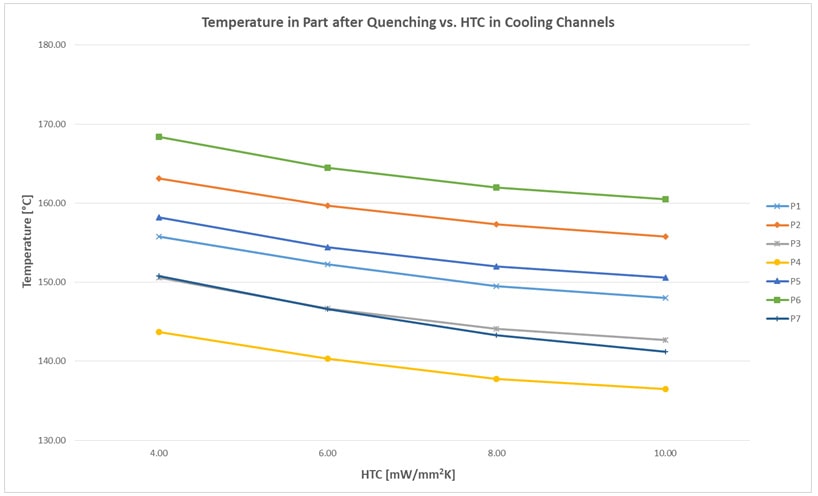


 Technology")
 Technology: Transforming Automotive Sustainability Through Innovation")

?")

 Process: Hot Forming Challenges Part 2")