
Introduction
Quality departments in the automotive sector are undergoing a major digital transformation. Manufacturing physical clamping devices is expensive, space-consuming, and labor-intensive. As a result, modern OEMs are digitizing their workflows and replacing traditional measurement methods with Digital Clamping, leading to six-digit-€ savings.
In traditional measurement setups, physical clamping devices hold parts in a stable position and ensure accurate inspections by representing BiW conditions. Digital Clamping removes the need for part-specific fixtures and replaces them with FEM simulation, which calculates how a part behaves under defined boundary conditions in vehicle position.
Conventional clamping has several disadvantages that can be addressed by digitizing the workflow. These include high costs for design, manufacturing, calibration, and storage; the considerable time required for iterative readjustment of clamping points; and further drawbacks such as slow change management, maintenance costs, limited reproducibility, and constrained accessibility.
Measurement in a Stress-Free State
One main task of Digital Clamping is to eliminate conventional fixtures. Even so, the component still needs to be scanned and measured in a precise and controlled manner. The process begins by capturing the part in its stress-free state. For this purpose, it is placed on a universal clamping device that can adapt to different shapes (see Figure 1) and provides at least three known contact points. Advanced measurement devices such as optical scanners then collect precise 3D surface data.
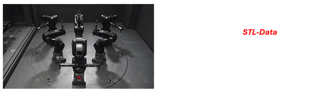
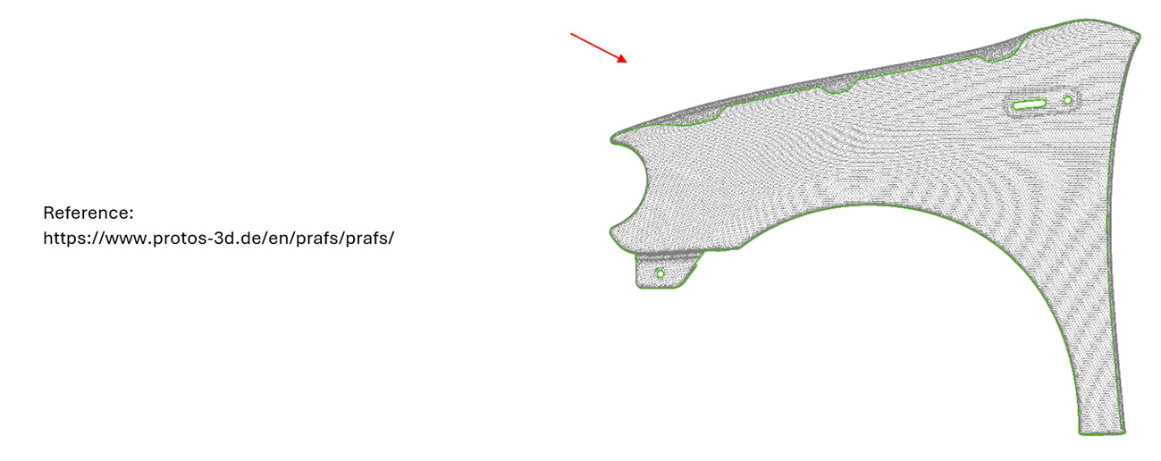
Figure 1: Measurement on a universal fixture in a stress-free state
Processing of Scan Data and Clamping Simulation
Polygonized scans of the sheet metal must first be prepared. This includes removing scan artifacts, reducing triangles, and reconstructing clean edges. The resulting scan of a given part typically deviates from the CAD-0 geometry for two reason:
- Springback from the forming process distorts the shape from the intended geometry.
- The fixation setup introduces gravity deformation on top of the springback.
If not corrected, gravity-induced distortions compromise clamping simulation accuracy. Therefore, scan data correction is a crucial Digital Clamping step and refers to compensating for displacements caused by the part’s weight. The principle of this correction is shown in Figure 2.
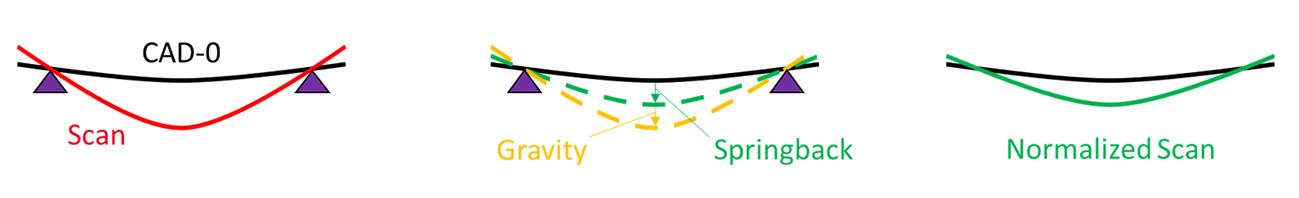
Figure 2: Principle of the scan data correction step
After normalization, the scan can be transformed into vehicle position and used for clamping simulations (see Figure 3).
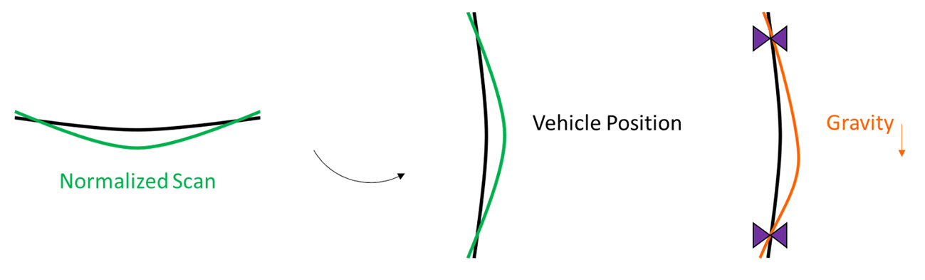
Figure 3: Principle of the transformation and the clamping simulation
Digital Clamping: Front Fender Example
Consider a front fender. Using software such as AutoForm Assembly, measurement compensation can be taken into account and real clamping conditions can be simulated.
Part-specific fixtures can be eliminated by simulating different fixture scenarios and digitally checking part quality after applying boundary conditions. Dimensional accuracy relative to the reference geometry and the resulting clamping forces can both be evaluated. Figure 4 shows an example of a digital clamping simulation.

Figure 4: Digital clamping simulation
Clamping concepts can be modified and evaluated within seconds. Figure 5 shows two additional simulation results in which certain clamps were deactivated.
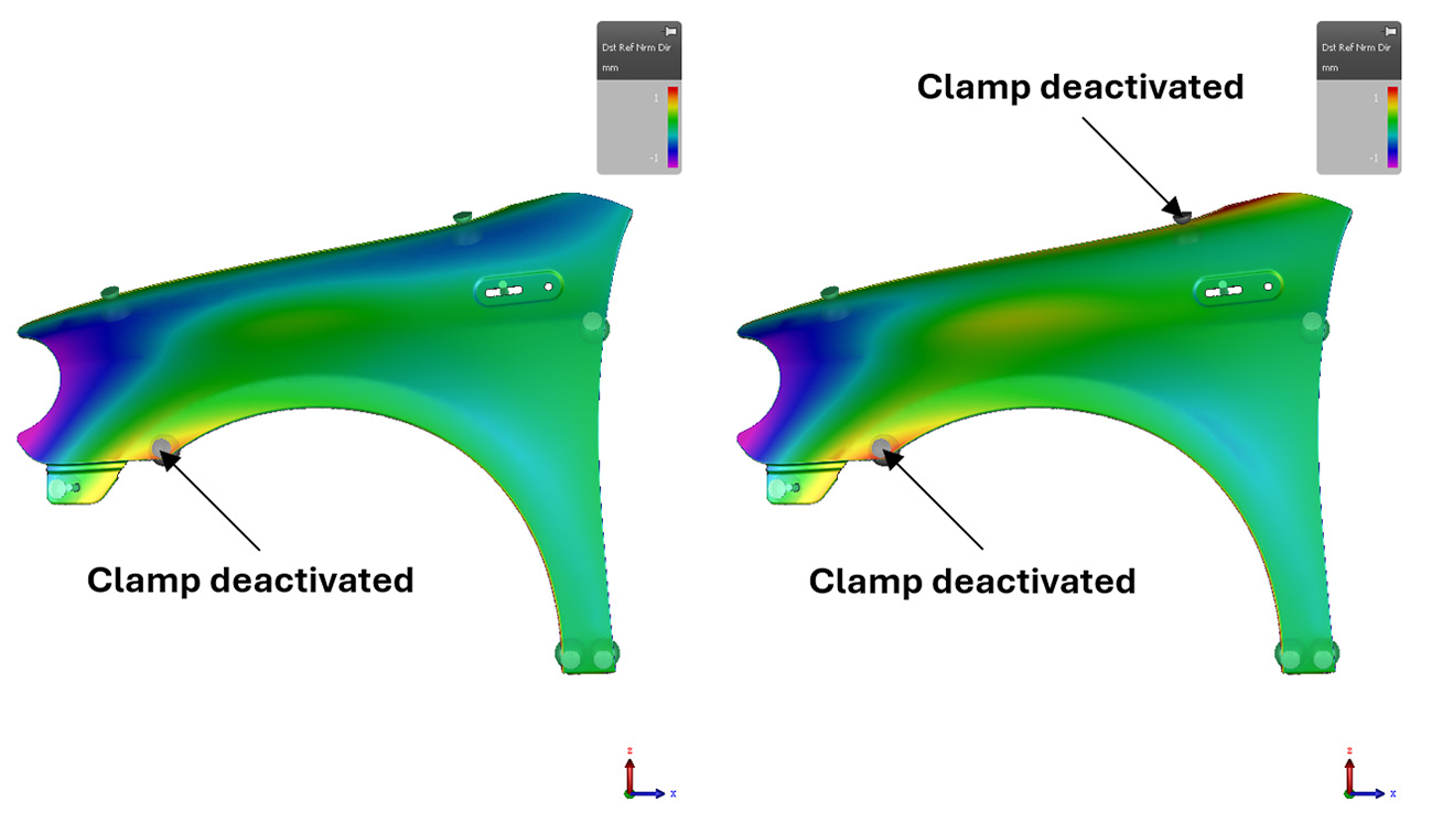
Figure 5: Digital Clamping simulations for different fixture scenarios
Based on the simulations, adjustments can be made to optimize the clamping process. This may involve refining clamping points or developing new clamping strategies to improve efficiency and quality.
As with traditional methods, the final step is to compare the digitally clamped state with the part’s design specifications using specialized inspection software to ensure that required tolerances and functional standards are met.
Various OEMs have investigated and validated this approach across many parts and materials. They have achieved an accuracy of ±0.2 mm for hang-on parts compared with results from scanning components clamped in physical fixtures.
To ensure seamless data transition, the integration of simulation software into the Digital Clamping workflow is shown in Figure 6. The exchange format is STL data, which can be exported and processed like scan data to create measurement reports.
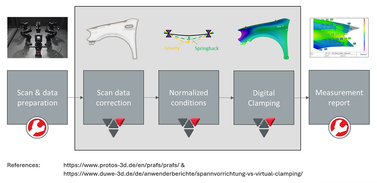
Figure 6: Digital Clamping workflow and software integration
Key Advantages
This approach offers several benefits, particularly in cost efficiency and process capability.
Significant cost savings can be achieved because part-specific fixtures are no longer needed. Fewer repeated measurements are required for different clamping plans, and change management becomes simpler since adjustments can be made without mechanical alterations. This allows an earlier start in the process chain and reduces the number of optimization loops.
Digital Clamping also provides excellent accessibility for optical measurements and offers ideal boundary conditions. Unlike traditional clamping methods, it lowers operator influence, resulting in more reliable and repeatable results.
Conclusion and Future Perspectives
Digital Clamping increases measurement reliability while significantly reducing costs and improving efficiency throughout the production process.
Integrating Digital Clamping into automated workflows is a promising direction. As industries adopt digital twins and automated quality control systems, Digital Clamping will become a key element of smart manufacturing.
By combining precision, efficiency, and sustainability, Digital Clamping is setting new benchmarks in quality assurance and metrology. It reflects the broader shift toward digital transformation and supports smarter, more adaptive manufacturing processes.


")


?")


