
Written in collaboration between engineer Paulo César Junior from Maxion Structural Components in Cruzeiro and engineer Wesley Aparecido from AutoForm, this article explores the main problems faced in stamping and how applying a digital process twin led to a significant reduction in scrap and rework rates, improving overall production efficiency.
Continuous Improvement Through Digital Process Twins
The Maxion Structural Components unit in Cruzeiro is a clear example of how digital engineering process twins can transform manufacturing efficiency. Since 2005, the company has used simulation to improving its stamping processes, integrating new features and evolving its methods over time. This approach has been critical in optimizing production, enhancing line performance, and ensuring continuous improvements. The engineering team at Cruzeiro demonstrates how this digital methodology was applied possible to optimize the production process of a crossbar component.
The Challenge: Forming a Complex Cold-Stamped Part
The component under study is a cold-formed serial production part with a 6 mm thickness and a tensile strength varying between 560 to 700 MPa. The combination of the product’s geometry and the material’s complex mechanical properties created significant challenges. Transitions, tight radii, and complex curvatures (Figure 1) made forming difficult and directly impacted product quality, leading to high scrap rates.
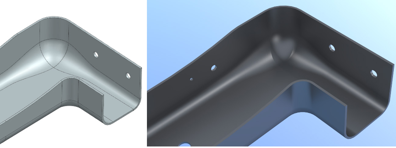
Fig. 1: Region of difficult forming
The main defect observed was excessive wrinkle formation (Figure 2). Some parts could be reworked (Figure 3), but when rework was not possible, they had to be scrapped. Excessive wrinkling caused overlapping material, which increased local deformation, leading to material hardening and eventual rupture.
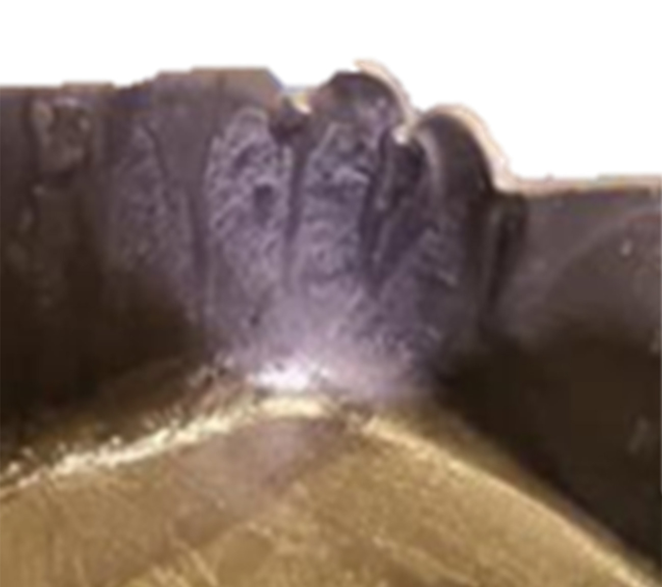
Fig. 2: Part with excess wrinkles (quality failure)
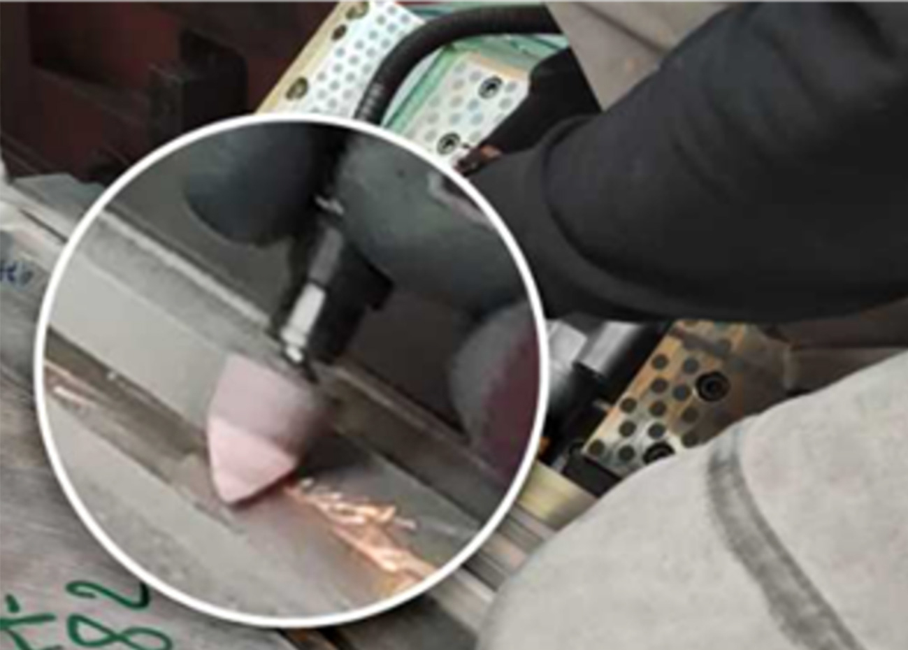
Fig. 3: Part reworking
In addition to the wrinkling issue in the product, there was another aggravating factor present. High thickness and tension generated by pressing the wrinkle against the walls of the die caused premature tooling wear, resulting in loss of the coating (Figure 4a). The tool maintenance team had to intervene frequently, welding the affected area (Figure 4b), then adding material for subsequent finishing and polishing (Figure 4c).
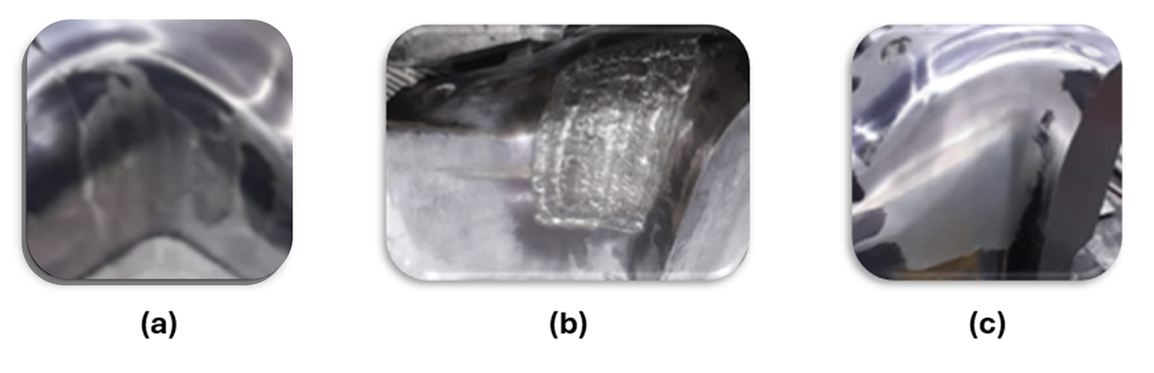
Fig. 4: (a) Worn steel, (b) Welded steel, (c) Polished steel
One of the methods adopted to support production in solving these issues was reverse engineering the tooling using a surface scanner and AutoForm Forming. The scanner made it possible to capture the actual condition of the tool, revealing variations in the distance between the die and the punch (Figure 5). Values close to 6 mm were expected, as this corresponds to the nominal sheet thickness. However, due to excessive pressure on the steel and material buildup in this region, the tool gap reached up to 7.5 mm in some areas.
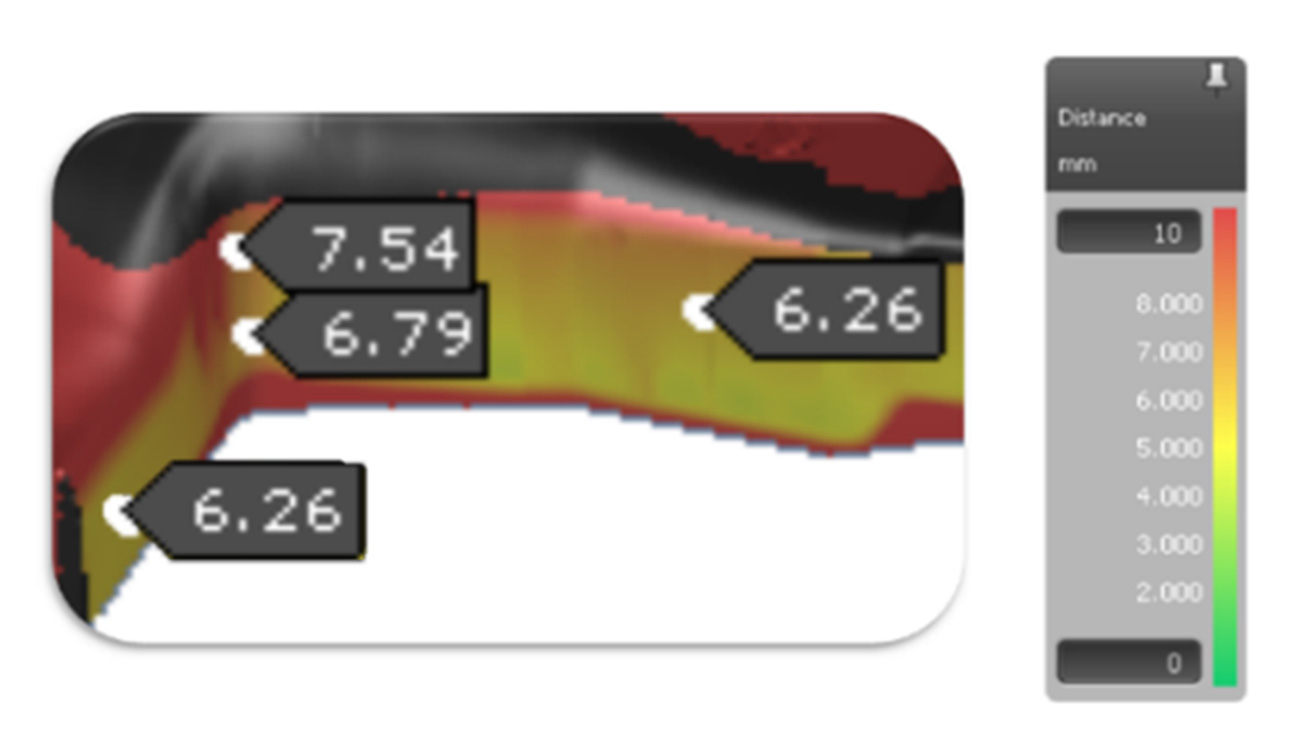
Fig. 5: Sheet gap between steel and die
After analyzing the scanned tool surfaces, all parameters of the real process were defined in the simulation: sheet placement, operating forces, sheet dimensions, friction, movement of the components, and cushion pin positions. To confirm that the virtual model matched real conditions, the simulated skid lines and wrinkles region were compared with the actual ones (Figure 6).
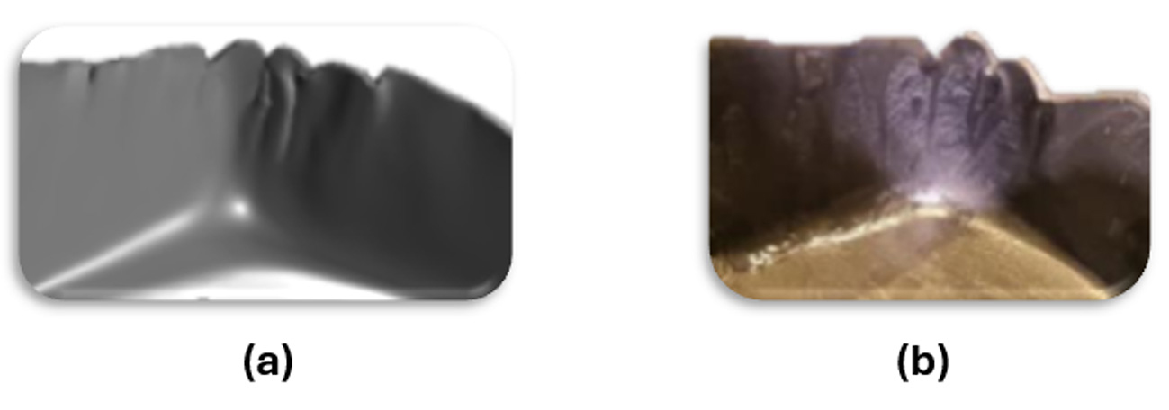
Fig. 6: Comparison – (a) simulated vs. (b) actual
Another criterion used for comparison was steel wear (Figure 7). For this, the AutoForm DieAdviser, TriboForm and Thermo plug-in modules were used. These modules improved the virtual model by enabling a more accurate friction model that also accounted for die heating effects.
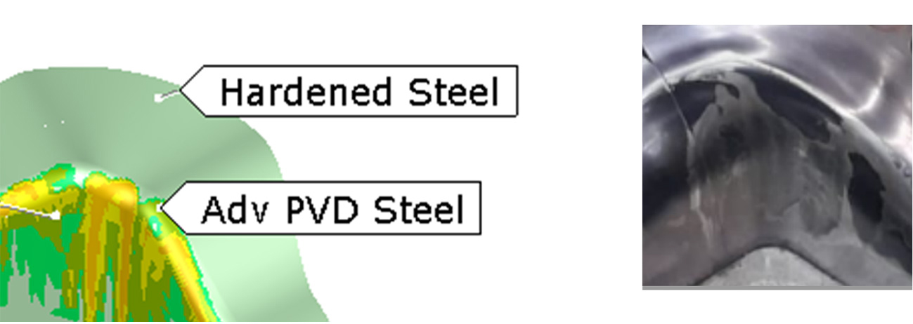
Fig. 7: Comparative tool wear – (a) simulated vs. (b) actual
With the virtual model validated, a virtual tryout was conducted to develop a definitive action plan to solve the problem. To support this plan, AutoForm’s advanced post-processing features of incremental simulation were used, such as “Minor Stress” (minimum principal stress), which made it possible to identify areas of high compression in the analyzed region.
To minimize compression effects, the first modification was to adjust the blank profile (Figure 8), as this was a less invasive change. However, this alone was not sufficient to eliminate the defect. Using another software resource, Die Face, a steel step was applied to reduce sheet metal compression at the point of contact with the die, ensuring a more uniform stress distribution along the region (Figure 9). Combining both approaches produced satisfactory results, which were forwarded to the tooling department for validation and implementation.
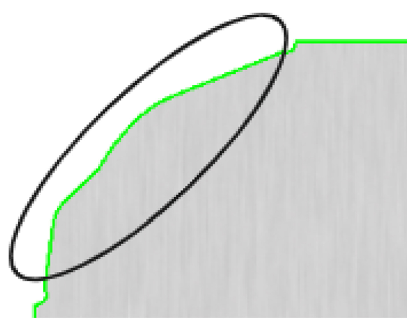
Fig. 8: Blank proposal – blank perimeter change
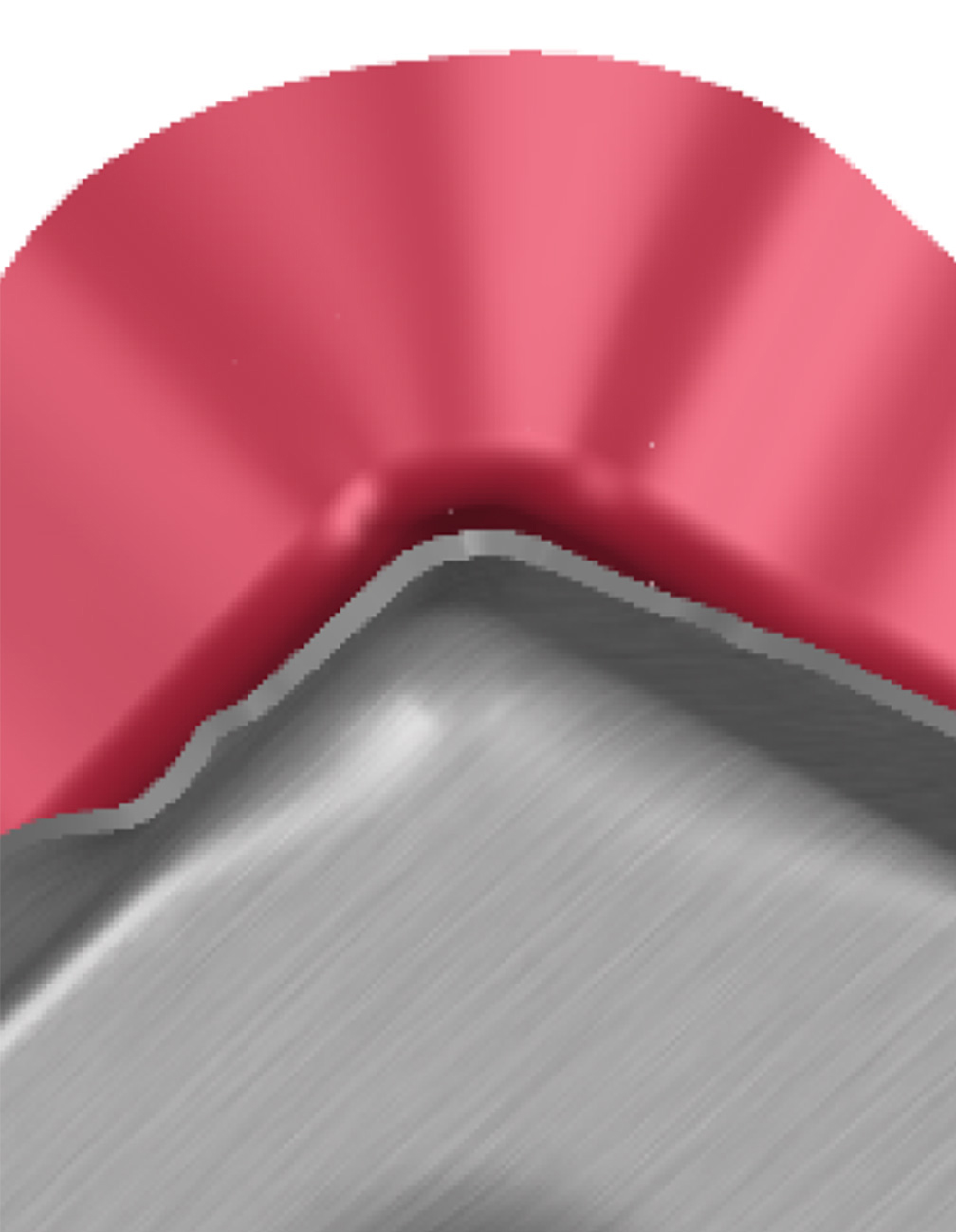
Fig. 9: Steel stepping proposal
Once the action plan was implemented, the results met expectations (Figure 10). In subsequent production, the scrap rate was significantly reduced and rework was completely eliminated, improving press shop efficiency and contributing to greater sustainability.
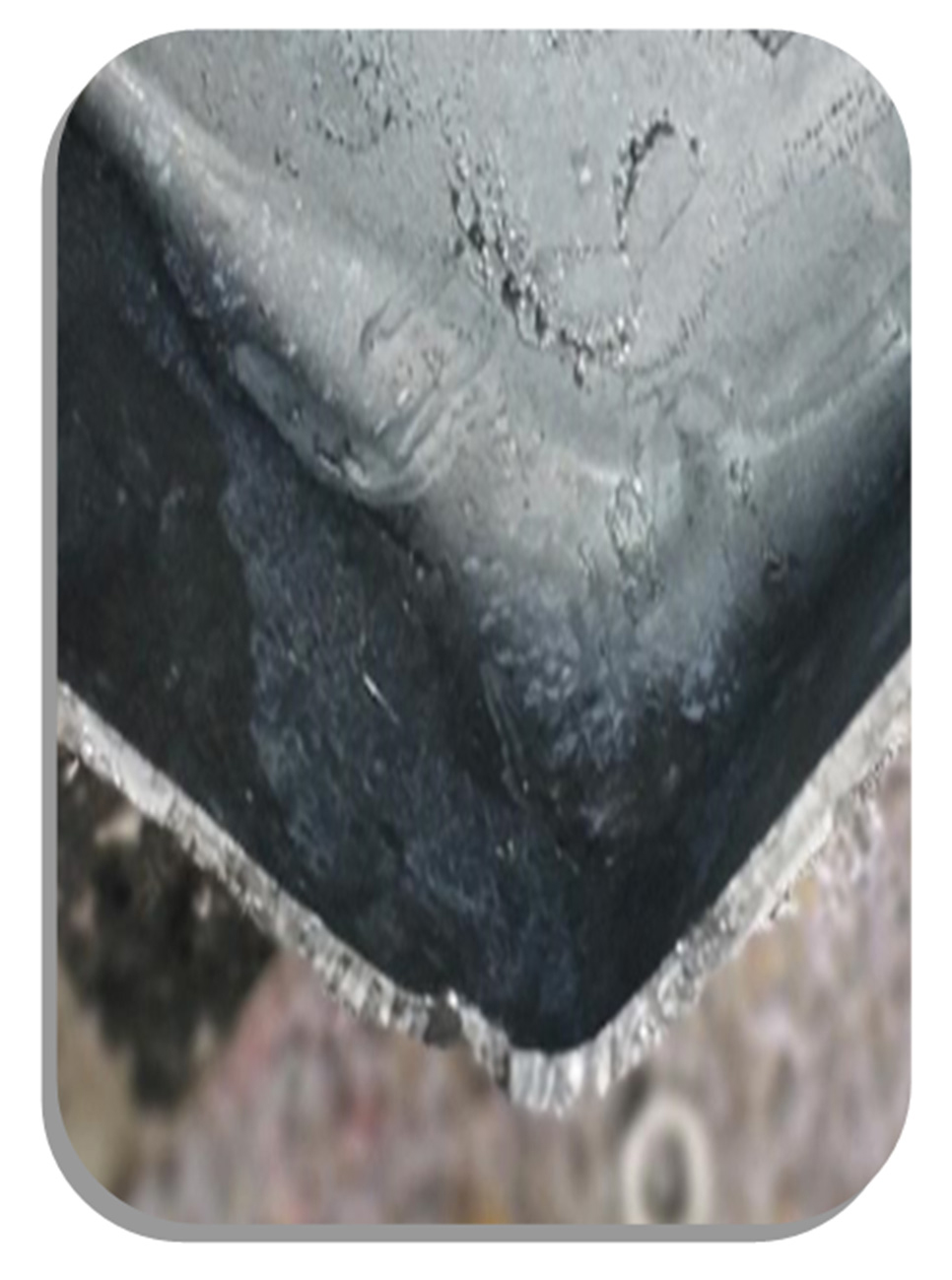
Fig. 10: Physical result after implemented modifications
As demonstrated, applying simulation to production enables effective modifications, since the entire study can be carried out in parallel with ongoing operations. Only after identifying the optimal solution is the proposal implemented in the tooling, eliminating trial-and-error interventions and resulting in significant gains. The example presented here is just one of many possibilities—others include blank reduction or improvements in CP and CPK indices to meet Part Submission Warrant (PSW) or PPAP validation requirements, greatly reducing the time needed to start production.
If you are interested in this approach, we invite you to read the article “Virtual PPAP Planning,” which explains how AutoForm can support PPAP planning by advancing numerous stages, optimizing both time and cost.
References
AMS. (30 of 03 of 2017). American Metal Specialties. Fonte: https://apiams.com/blog/early-history-sheet-metal/
Texas Iron and Metal. (28 of 10 of 2024). Fonte: https://www.texasironandmetal.com/metal-processing-through-centuries/


?")


