
Introduction
Stamped outer panels are very prone to unwanted plastic deformation during subsequent moving, carrying, and inspection after stamping due to their poor stiffness. These deformations may lead to unacceptable dimensional and surface quality issues. Therefore, it is important to detect these deformations at an early engineering stage.
To achieve this goal, we must accurately evaluate the stiffness of panels under realistic loading conditions. However, there is currently no systematic method for evaluating the critical stiffness of stamped outer panels. This paper explores a novel evaluation method for assessing the critical stiffness of outer panels using AutoForm Forming and establishes a stiffness evaluation standard for automotive front door outer panel stamping.
1 Stiffness Simulation Analysis Under Gravity Load Only
Under actual gravity conditions, the relatively low points at the four corners of the stamped outer panel come into contact with the supporting surface. If the panel’s stiffness is insufficient, the Class-A surface may exhibit defects such as surface low under gravity loading, directly affecting the part quality.
This study applies the self-positioning (locating) function in AutoForm’s measuring OP, using a flat plate as the support tool to analyze contour and shape changes of the front door outer panel under gravity. Elastic deformation and vibration within the material’s elastic range can partially reflect the stiffness of the stamped panel. Using the surface lows command, we can inspect the stoning and curvature result before and after gravity loading. In this way, stiffness-deficient areas can be qualitatively identified and their influence on part quality assessed. In theory, regions with lower stiffness exhibit greater curvature changes, while stiffer areas show minimal variation, resulting in less abrupt transitions in the stoning analysis. Figure 1 illustrates the gravity loading condition of the front door outer panel on a flat plate.
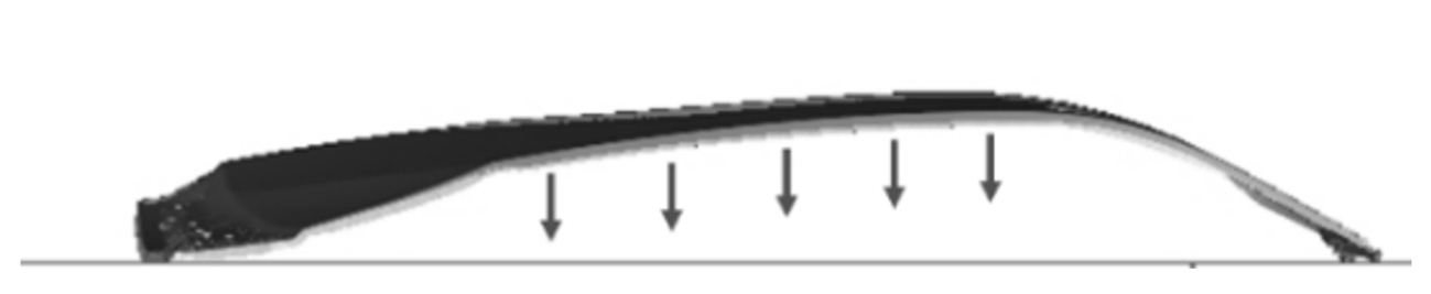
Figure 1: Gravity loading condition on flat plate support
The stiffness analysis results for front door outer panels of different NIO vehicle models under flat support conditions are shown in Figure 2. As observed, the larger the red-orange-yellow zone (color gradient indicates severity), the more severe the deformation. Under gravity loading, areas with insufficient stiffness on the stamped front door outer panel are mainly distributed near the A-pillar and B-pillar on both sides. Due to its highly arched design, model B’s door panel exhibits better overall stiffness, whereas model D performs the worst, showing significant curvature changes under gravity and a higher risk of actual surface low—especially near the B-pillar. This qualitative stiffness evaluation will be verified in the subsequent quantitative pressing deformation simulation.
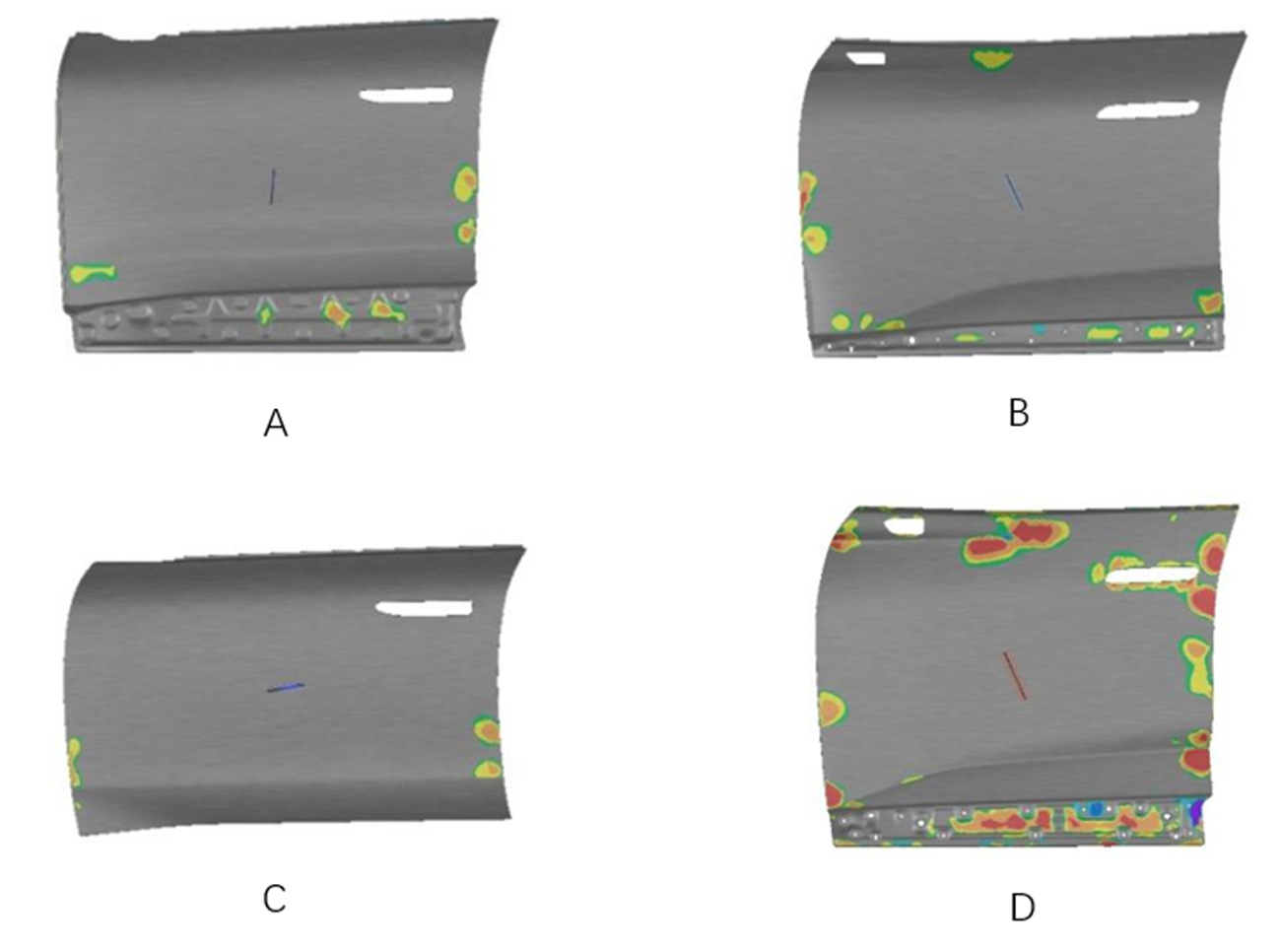
Figure 2: Surface low of NIO’s different car models under gravity
2 Stiffness Evaluation Based on Press Deformation Simulation
This study selects the high-point areas with the maximum curvature near the B-pillar on the front door outer panel to construct the pressing surface. The selected area is shown in Figure 3. Referring to the pure gravity deformation state from the above simulation, a cylindrical pressing surface with a diameter of Φ160 mm was constructed in CAD, keeping the deviation between the constructed pressing surface and the pure gravity state within 0.01 mm.
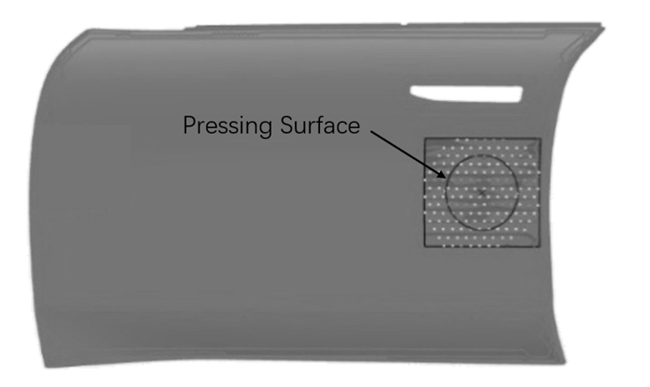
Figure 3: Pressing areas selection
The schematic of the pressing deformation simulation is shown in Figure 4. A flat plate is defined as the lower tool, while the constructed pressing surface is defined as the upper tool. Pressing analyses were conducted on the front door near the B-pillar. A pressing force of about 10 N was applied to the upper tool. After simulation, the displacement of the pressing tool was measured in the post-processing results (Figure 5).
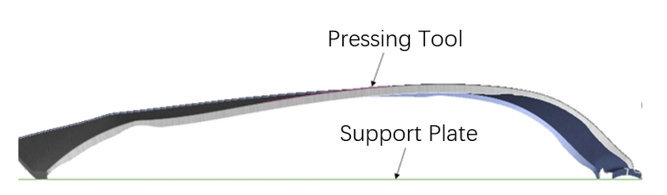
Figure 4: Schematic of the pressing deformation simulation
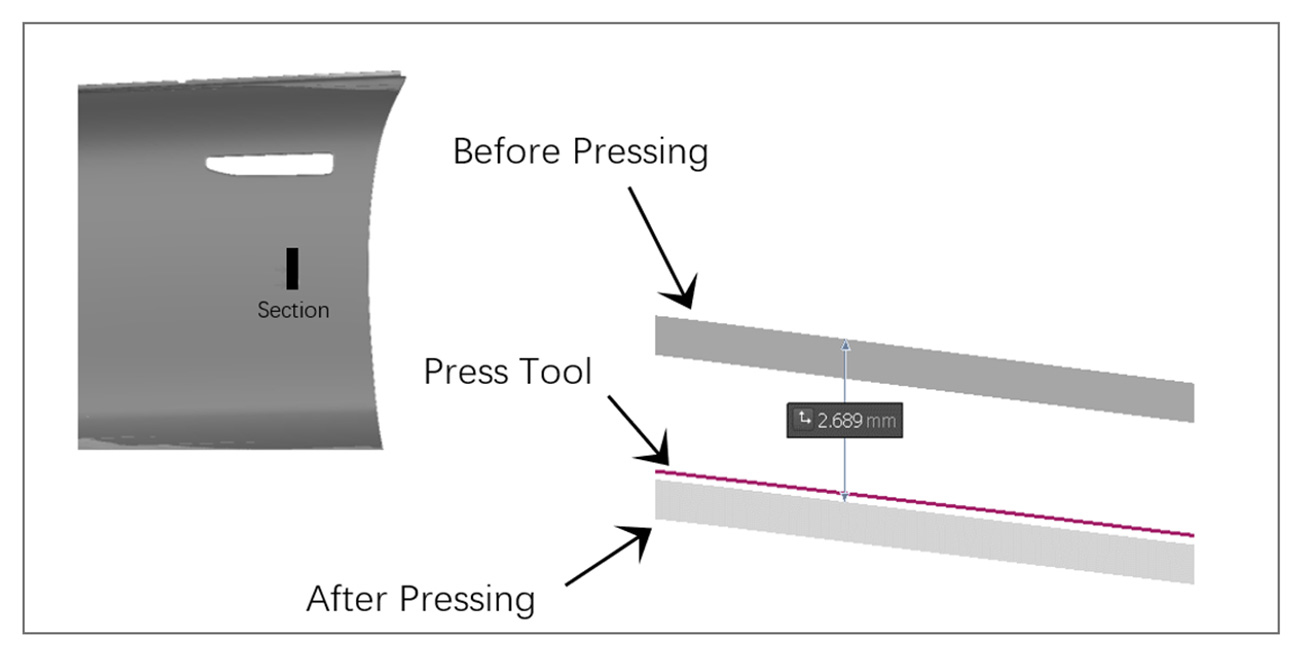
Figure 5: Final displacement of pressing tool
Using this method, pressing force and displacement for various NIO vehicle models were measured under similar conditions. The ratio of pressing force to displacement was used as the stiffness evaluation index for the stamped outer panels. The stiffness coefficients near the B-pillar region for each front door outer panel are summarized in Table 1.
The data show that panels with better inherent stiffness exhibit smaller displacement under the same pressing force. Based on the ratio of pressing force to displacement, the stiffness evaluation index can be indirectly obtained.
Table 1: Summary of the testing results of different car models at B-Pillar
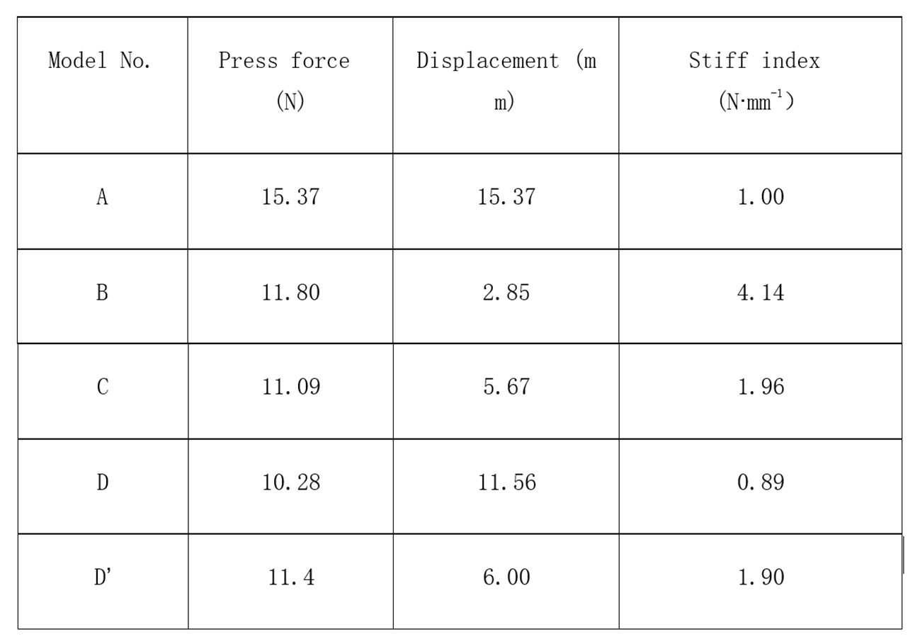
Note: D’ represents a modified version of the original Model D component, where the flange length in localized weak areas was increased to enhance stiffness.
The preliminary stiffness evaluation results for the B-pillar region are: B > C > A > D
This ranking based on pressing stiffness aligns with the surface low distribution trend under pure gravity loading shown in Figure 2.
3 Physical Verification
3.1 Stiffness Test Verification for Model D
For the B-pillar area of Model D’s front door outer panel, a pressing test under equivalent conditions was conducted following the simulation boundary conditions. A static pressing force of 10.78 N (equivalent to a 1.1 kg object) was applied. Dimensional data before and after pressing were collected using scanning equipment. The displacement distribution is shown in Figure 6. The results indicate that pressing displacement on the B-pillar side reached 11.28 mm, giving a stiffness coefficient of approximately 0.96 N/mm (10.78/11.28). (Note: In the scanned data, the pre-pressed product was used as the reference plane. If the post-pressed product appeared below this plane, negative values were displayed. The discussion focuses on displacement magnitude, ignoring sign.)
The experiment led to the following conclusions:
- The stiffness coefficient on the B-pillar side is relatively low, indicating poor stiffness, consistent with simulation results
- The stiffness coefficient remains below 1.0 N/mm.
- These findings match the surface low analysis under pure gravity loading, confirming inadequate stiffness near the B-pillar.
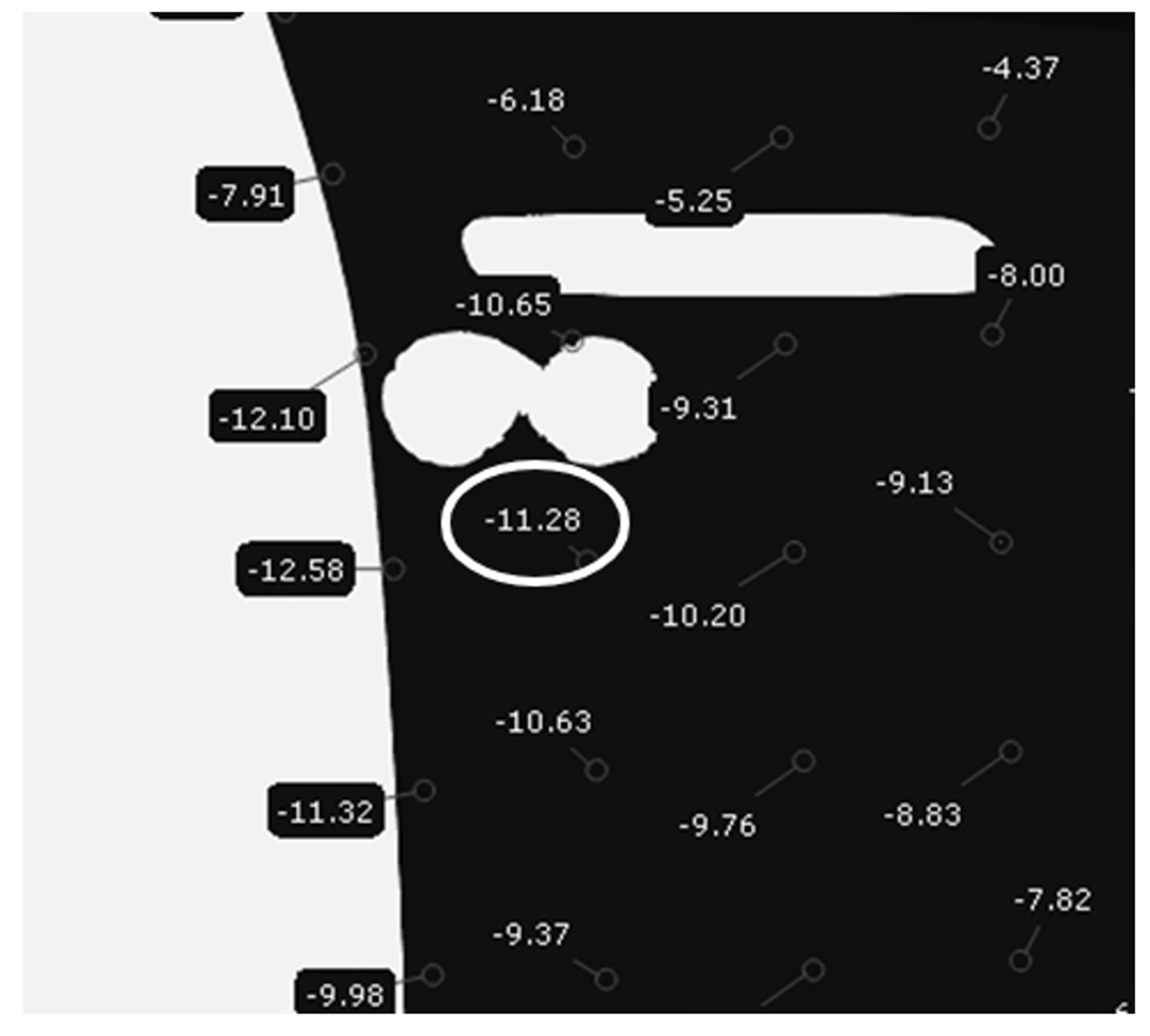
Figure 6: Displacement of real panel’s B-pillar under pressure
3.2 Stiffness Optimization and Verification for Model D
To improve stiffness in the B-pillar area, the local flange length on the B-pillar side was extended by 1.5 mm. A follow-up pressing simulation was conducted to evaluate the modified design (Model D’). As shown in Figure 7, the simulated pressing displacement was reduced to 6.00 mm, increasing the stiffness coefficient to 1.9 N/mm (11.4 N / 6.00 mm). This confirms that extending the local flange effectively enhances the part’s stiffness.
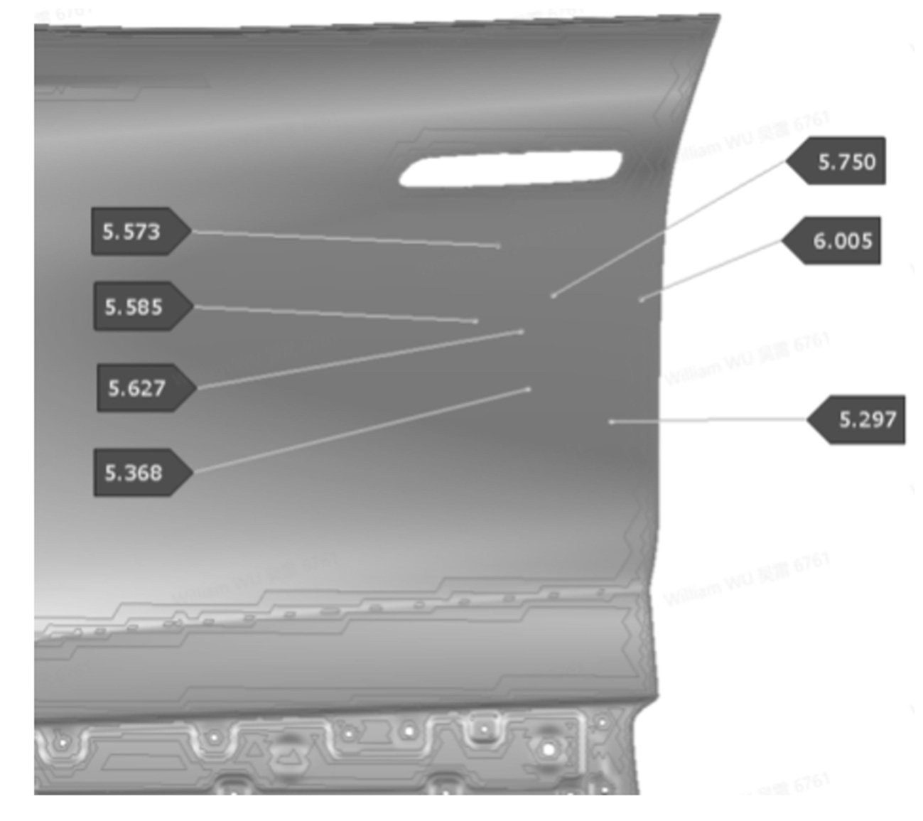
Figure 7: Simulated displacement of Model D’s B-pillar area
After confirming the improvement virtually, the physical part was modified by extending the flange as shown in Figure 8, with a local extension of approximately 1.5 mm. A physical pressing test was then conducted using the same load of 10.87 N. The resulting deformation distribution is illustrated in Figure 9, with a maximum deformation of 6.77 mm. The stiffness coefficient after modification was calculated as approximately 1.60 N/mm. This value is close to the simulation result of 1.9 N/mm, demonstrating good consistency and further validating the reliability of the stiffness analysis.
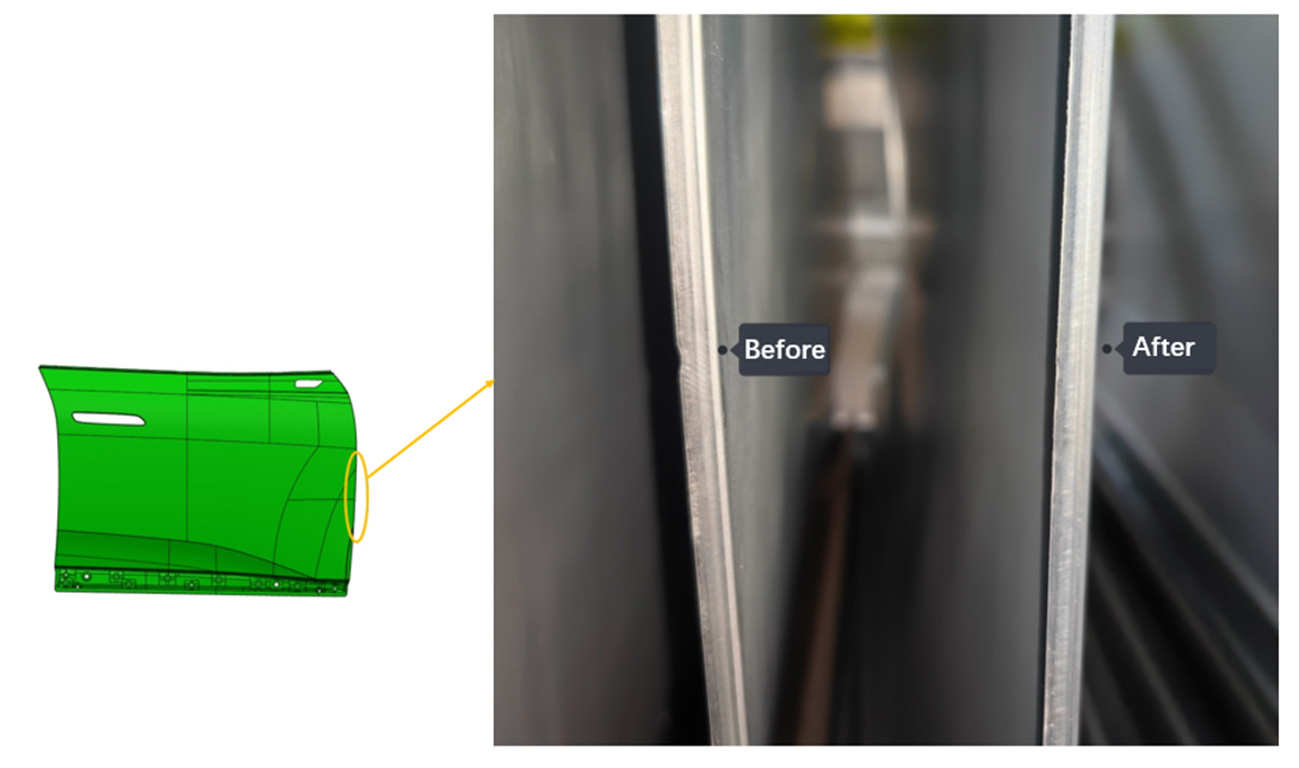
Figure 8: Elongation of local B-Pillar flange
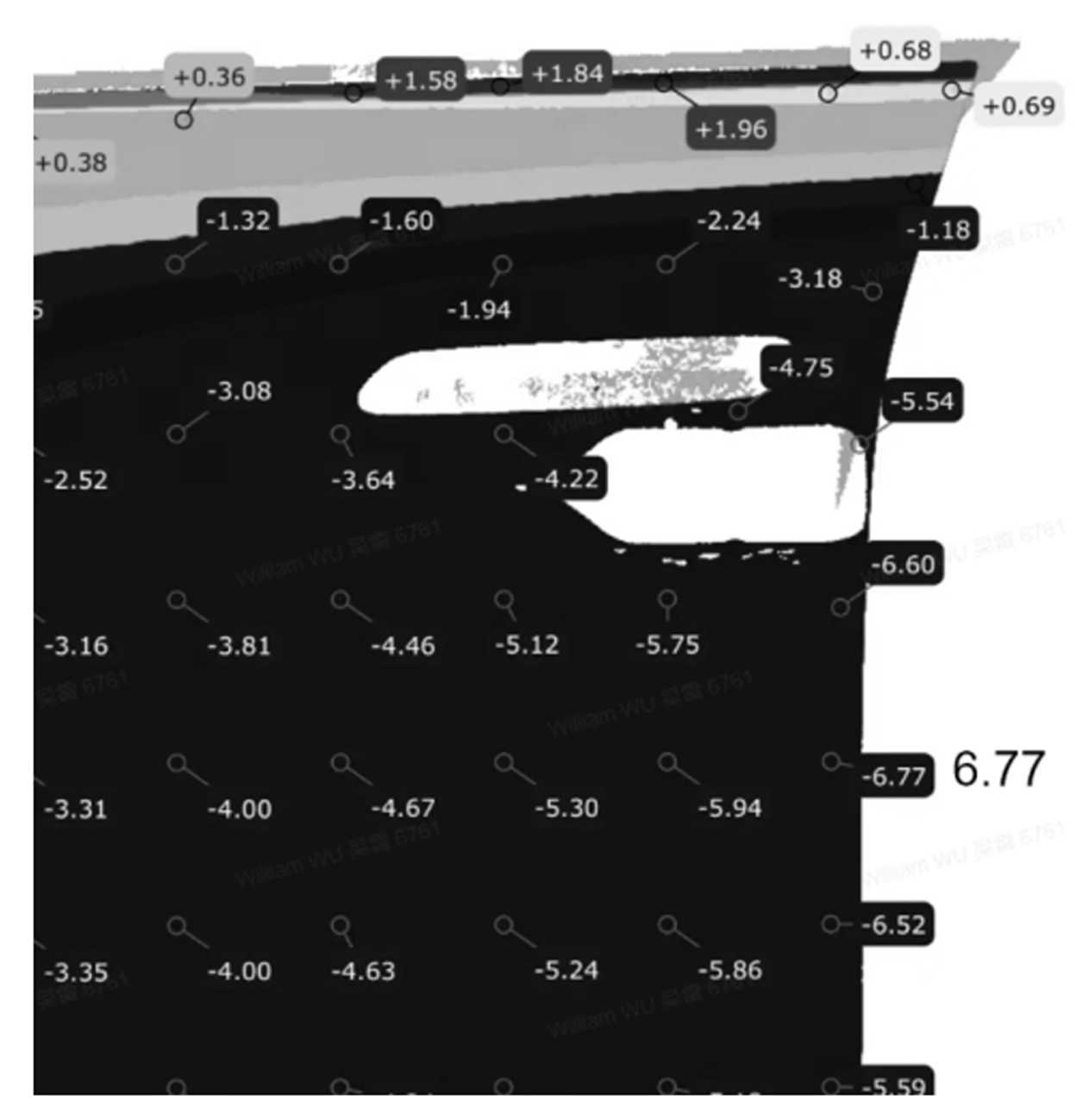
Figure 9: Pressing displacement of optimized real panel
4 Conclusion
Insufficient local stiffness of stamped outer panels leads to plastic deformations during production, storage, and transportation, affecting surface quality. This study establishes an evaluation method based on stiffness coefficients using AutoForm simulation.
(1) Under pure gravity loading, surface low analysis can identify low-stiffness areas.
(2) In pressing deformation analysis, the ratio of pressing force to displacement (stiffness coefficient, N/mm) provides a quantitative index that accurately describes stiffness, consistent with gravity-based surface low results.
(3) Physical pressing verification of the front door outer panel of Model D further demonstrates the rationality and effectiveness of the pressing stiffness analysis.
(4) Based on virtual analysis of pressing stiffness, the stiffness of the front door outer panel of Model D was effectively optimized by increasing the local flange length.


?")


