
Essential Practices Towards Reliable Simulation Based on Outcomes
In this interview, Adithya Ramamurthy, an Application Engineer at AutoForm USA, describes three essential practices geared towards reliable simulation outcomes for springback compensation. Do not skip these steps if you want to ensure accurate simulations with AutoForm-Compensatorplus.
Adithya began ‘Due to the high number of questions I receive regarding this matter, I realized it’s time to broadcast the solution widely. Achieving dimensional compliance of stamped panels is the “holy grail” for sheet metal stampers. Digital engineering and simulation tools are crucial towards this goal, but they need to be applied systematically, and with unflinching diligence in minimizing the “difference” between digital and physical “realities”. Bernd Glassbrenner, a Senior Process Consultant with AutoForm Engineering GmbH, alludes to these in an earlier post here.
 Execution of digital compensation and validation involves a lot of details; of these, the following aspects deserve to be singled out for very special attention and handling.
The first is replicating the intended physical conditions of dies and processes during digital engineering and simulation. Second is ensuring the accuracy of computational responses to the defined die and process conditions. The third is the process of compensation itself – what to compensate, and how. It’s not that users are skipping these steps so to speak, but rather, a certain amount of effort needs to be put in to execute the first step properly if not, a mismatch will arise between reality and their settings.
Step 1: Replicating Physical Conditions
‘In the design mode, we build process and dies in the digital world, progressively optimizing these using simulation to produce parts that are acceptable on all quality metrics. Design and simulation need to be carried out with utmost diligence to reflect the dies and process that we intend building and operating in the physical world, in all essential detail: die shape and clearances, tonnages, blank, binder and pad gaps, binder bearing, etc. No detail may be ignored in the validated data finally released for die build, machining and die making. ‘An important detail that is oftentimes not accounted for during digital validation is the compensation of draw dies for nature shrinkage of the drawn sheet metal: draw dies need to be scaled, the adequacy of scaling needs to be validated in simulation, and the validated amount of scaling needs to be faithfully incorporated while machining draw surfaces. Last but not the least, tryout or production material needs to be accurately represented in simulation based on test data.
Step 2: Ensuring the reliability and accuracy of simulation outcomes
‘Hand-in-hand with the diligence applied, as above, to the representation of physical die and process conditions, simulation control parameters proven to generate the most accurate results need to be employed. Sheet and tool surface geometries are represented in the simulation world as faceted meshes. Tool surface meshes need to be adequately refined to capture all essential geometry elements, even the finest as designed. Sheet mesh needs to show a commensurate level of refinement, however, never finer than the tool mesh; this ensures that tool mesh imperfections, if any, are not inadvertently captured in the sheet. Simulation software have pre-configured sets of control parameters that accomplish all this and more, and the appropriate set needs to be reliably applied. It is also crucial, prior to reading simulation results for formability and other outcomes, to check for any and all warnings generated, and countermeasure these: outcomes from “unhealthy” simulations, carrying critical warnings cannot be relied upon. By the same token, outcomes showing less than acceptable part quality are not ready for any springback countermeasures or compensation – essential part quality needs to be guaranteed first, before addressing dimensional concerns.
‘When all of the above is said and done, utmost care needs to be applied on how the formed sheet is held, or “fixtured”, for its springback to be measured in the simulation. Prior to compensation, it is important that the holding scheme, comprising pilots, nets, and clamps, does not distort the panel, or in any way change the natural springback response of the sheet. If springback is not measured right, countermeasures and compensation will be inadequate at best, and incorrect at worst.
Refer to the short overview of Springback Best Practices recently published in the Metal Forming Magazine 2018.
Step 3: Compensation Done Right
“Ok, ready to compensate!” Are we really?? Compensation is interesting to apply in simulation, and is exciting to validate progress of; however, before waving the “Compensate” wand, it is useful to gather some information and to “strategize” the approach.
- How much springback is observed? Is this “compensatable” without substantively modifying die process, formability, etc.?
- What is the nature or mode of springback? Curl on sidewalls? Oil canning? If yes, “compensation” will be a walk down a spiral stairway to nowhere … These modes of springback may be recognized in simulation outcomes, or from experience, and they require “countermeasures”, applied to process and/or processes. The earlier this is realized, the more “affordable” it will be to apply the necessary changes.
- How does springback evolve as the sheet progresses through the lineup of forming and trimming stations? What stations definitely need to be compensated? Which ones can be maintained nominal?
- And, how repeatable are the results of springback? How narrow, or wide, is the range of springback when the panel meets the reality of uncontrolled changes over production – material, gage, lubrication, positioning, dimensions, etc.? Such changes are typically within ranges deemed acceptable, but are often sufficient to compromise the robustness of panel springback, and therefore any compensation.
Beyond the steps outlined earlier, further “improvement” to the simulation set up becomes necessary oftentimes to ensure panel nesting, and to minimize panel crushing, as it moves from the initial draw to secondary trim and form stations. Incorrect nesting and crushing of panel under trim/form pads leads to unintended forming of the sheet in these stations, and as can be imagined, this can lead to changes in springback which is very difficult to address. This can also degrade springback robustness.
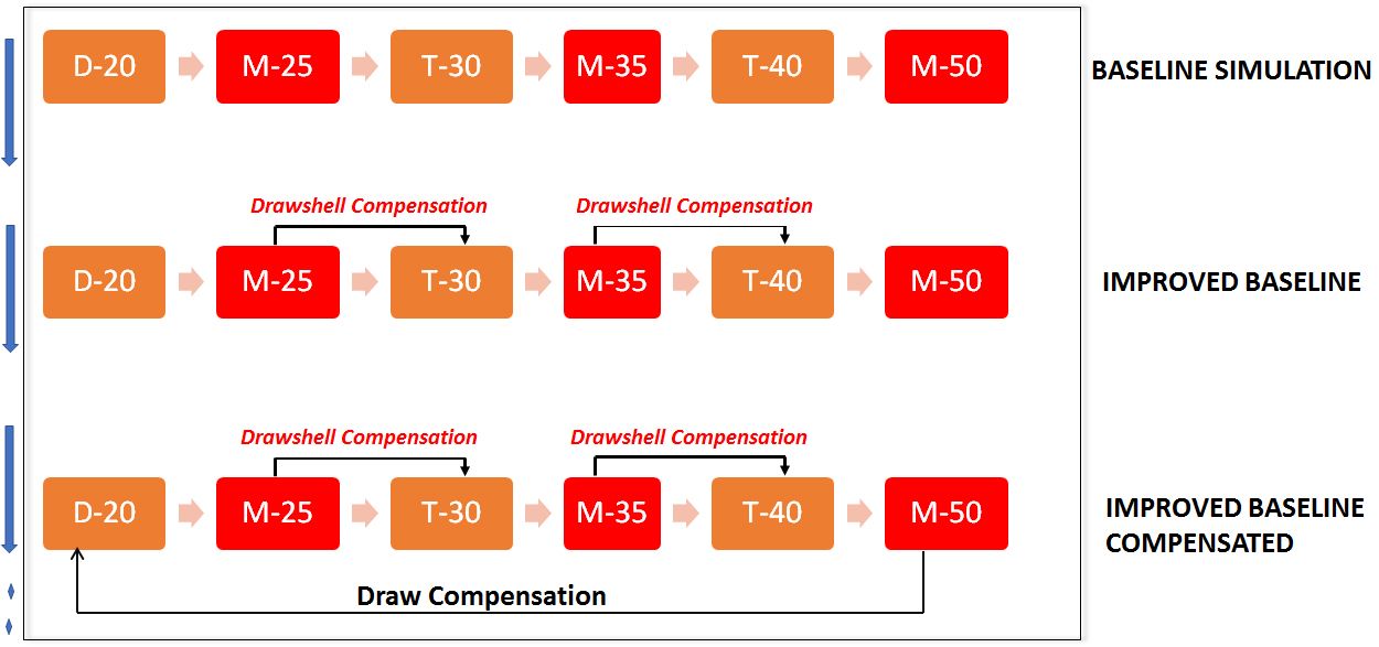
Fig 1: Example of compensation processes carried out by AutoForm
This “improvement” is a careful change to the post and pad surfaces of secondary stations that follow the initial draw: these surfaces are morphed to carry the exact shape of the sprung sheet metal coming off the prior draw/form (even trim) station, to ensure panel nesting on post, and minimize crushing under the pad. And the overall process is made significantly more robust, with reliable springback predictions. Such morphing is labeled “drawshell compensation”. Of the many strategies for compensation available in AutoForm it should be said that while this particular route is indeed a little more work before real compensation can be initiated, it shows strong benefits to reliable and robust compensation outcomes.
When all the diligent and detailed digital engineering is faithfully replicated in the physical world, a strong payoff in terms of cost, time and quality of panels is assured.
From FormingWorld: thank you Adithya for this insightful article. For new readers, stay informed by signing up for our blog. We’ll send you one email per month on our top four posts!


?")


