By Hironori Imai, Senior Application Engineer, AutoForm Japan.
In recent years, stamping simulation has become indispensable for the design and creation of stamped parts, the assessment of formability and the prediction of issues for dimensional accuracy, which covers dimensional deviation and/or surface defects.
While new materials and new methodologies are being introduced the demand for cost reduction is growing, making highly accurate simulations even more crucial. To effectively utilize the simulation, it is on the one hand decisive to model physical conditions as accurately as possible in virtual model. On the other hand it is also important to focus on the post processing, meaning the evaluation of the results, the analysis of the behavior of the actual panel in the measurement device, and how such behavior can be investigated by using simulation.
Importance of the part checking fixture
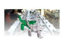
Both in simulation and in reality, one of the most important factors that need to be considered to determine the amount of springback is the holding condition of the panel. To measure displacements of the panel due to springback (or the distance from reference) a checking fixture with locating pins and clamps is commonly used; pins and clamps hold the panel in position so that its deviation can be measured from the reference geometry.
If the holding conditions are not appropriate, the panels may deform significantly due to gravity, making it impossible to measure the springback accurately. Therefore, it is very important to evaluate and optimize the stability of the checking fixture. Let’s examine how the checking fixture stability may be evaluated and improved by using AutoForm.
Evaluation of the panel measurement conditions
In most cases, the final condition of the checking fixture is designed by using the assembly conditions as a reference. Hence it is difficult to make changes to the fixture for stamping engineering reasons alone. On the other hand, if the assembly condition is “excessively constrained”, springback compensation will become difficult to converge within reasonable a time frame. Therefore, in these circumstances a special clamping concept (Minimum Clamping Concept) is created only to support the compensation process in stamping engineering. This MCC is required to have a similar orientation than the real measurement device to consider the gravity direction appropriately. As of Workflow / Tool Buy-Off specification, this might be e.g. tooling position, hemming position or car position dependent on subsequent processes/departments.
In this post, special attention is paid to the orientation of the fixture in tool position which might be used for a certain range parts (fender, body side outer, etc.). It supports the panel at some points on the design surface, rotated 90 degrees from car position in order to measure springback at the end of all operations easily. It is not allowed to have the checking fixture in vehicle orientation to satisfy buy-off conditions. Here we determined the supporting position that has the least influence of deflection driven by the gravity, when the panel deforms due to gravity while being placed at 90° from the vehicle orientation.
If the dimensional accuracy of the panel in the defined orientation is achieved by sufficient support of gravity on the fixture a robust measurement condition is realized, leading to the reduction of man-hours needed to modify the panel at assembly due to the accuracy changes.
A pre-deformed blank is used to determine the supporting conditions. The pure stiffness analysis is run from the product data that contains no forming history, in order to distinguish the springback deformation arising from the process and the deformation from gravity. In terms of AutoForm software, an “M” (measurement) operation is defined and only springback with boundary conditions is calculated. Only product data is needed and it only takes a few minutes.
Number of panel supports
Pictured below are positions to support the panel and material displacement of the panel on an initial condition. The supports are placed in the assembling position of the structural area, and on the design area they are placed at the end of pillars.
As shown in the figure, the rear side of the panel cannot support the gravity and is deformed by more than 1mm in negative direction of part normal.

Fig. 1 Material displacement in normal direction by gravity with the initial fixture holding condition
With a clamping concept like this it is required to have a large amount of compensation due to gravity effects alone. If such large amounts for gravity compensation need to be considered there is an additional risk to change curvatures in the panel while creating the compensated surfaces. The recommended workflow therefore not only considers springback reduction by process parameters (e.g.: reduce deviation caused by stresses) but also possible adjustments of the measurement concept (e.g. to reduce/eliminate gravity influence – which is main topic of this post.) Therefore the fixture holding condition is modified to avoid the deformation, and the result is shown in Fig. 2.

Fig. 2 Material displacement in normal direction by gravity with the manually modified fixture holding condition
If such a gravity influence is found only when measuring the dimension of the real part the man-hours required to find a solution would be enormous at that point. Thus, it is extremely important to examine the conditions in advance in order to define countermeasures beforehand.
Improvement of the position of the supports
Although a significant deterioration of accuracy can be avoided by examining the number of supports, the accuracy is still not within the typical allowed tolerance of ±0.5mm. In particular, the torsion at the rear side is outside the dimensional tolerance.
That means, if this panel will be 100% compensated without considering gravity influences, it still faces dimensional errors due to this gravity deformation. To further optimize these, the supports 3, 5, 6, 7 and 8 are moved laterally to improve the supporting conditions.

Fig. 3 The range of Sigma variation for the positions of support
Several issues are defined with respect to ±0.5mm tolerance of material displacement in normal direction and resolved by using AF-Sigma. Again, simulation starts from pre-formed blank without forming history, material displacement represents deformation due to gravity alone.
Fig. 4 shows the amount of the panel distortion after resolving the support positions. The significant twist at the rear side arising from gravity has been eliminated, and the entire panel is within the required dimensional tolerance of ±0.5mm.

Fig. 4 Comparison of manually modified versus improved result by using Sigma
As a quantitative rating, Fig. 5 shows a comparison of Root Mean Square (RMS) values at the measuring points. It is obvious that the dimensional error at the rear part of the panel can be decreased.

Fig. 5 Measuring points and transition of errors
Summary
In practice, only product data is used to run the stiffness analysis in order to assess and reduce risks in the panel measurement caused by gravity. Furthermore, the number of supports can be modified to avoid significant accuracy deterioration. Lastly, the supporting positions are improved by using AutoForm-Sigmaplus to minimize the gravity deformation of the panel on the fixture.
Thank you Hironori Imai for this most informative post. New readers, you can get more articles like this by signing up to our blog. We only send one update per month covering the latest top posts.


