We have been saying it for some time. More and more automotive companies are demanding a more accurate description of tribology conditions in forming simulations to prevent production issues and increase overall production stability for higher quality parts. In this blog post, forming simulations on a Renault Talisman inner trunk part are presented, demonstrating how simulation accuracy is increased when accounting for actual tribological conditions. A comparison between conventional simulations and those using the TriboForm model is shown.

Fig 1: The all new Renault Talisman & trunk lid inner part.
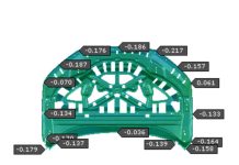
Groupe Renault, Tata Steel, AutoForm and TriboForm joined forces to examine the cause of production issues observed on the trunk lid inner part, which faced wrinkles and splits. The stamping process of this highly complex part takes place in the Renault press shop in Douai, France. However, the stamping process faced some issues, whereby the critical regions are indicated in the dashed boxes (Figure 2). These areas faced splitting or critical thinning (red) and wrinkling (blue) which showed up in the final product, making the part unacceptable for release.

Fig 2. Trunk lid inner part, with splits or critical thinning (red) and wrinkles (blue)
At the time, Groupe Renault used a constant Coulomb coefficient of friction of µ = 0.15 for steels in stamping simulations. Then, to more accurately account for friction and lubrication, the TriboForm friction model was put to the test, using the TriboForm Plug-In which brings the model into use in AutoForm. As a result, forming simulations were performed using friction conditions that vary locally and in time. As an example, a snap shot of the friction conditions at the end of the stroke for the trunk lid inner part is shown in Figure 3. Clearly, friction is not constant but dependent on local conditions like pressure, velocity, strain and interface temperature. It shows that friction in the draw bead area, where local contact pressures are very high, can be as low as µ = 0.03. On the other hand, in the blank holder region friction coefficients are seen which are closer to µ = 0.13.

Fig 3: Local friction conditions at the end of the stroke for the trunk lid inner part
Production vs. Simulations
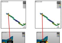
Looking at a comparison of the simulation results using Coulomb friction and TriboForm friction, one immediately sees several differences. Figure 4 shows the draw-in results. The production part has ended up with a smaller draw in than the simulation predicted using Coulomb friction. On the right side is the TriboForm model in action. The outline of the simulated part is now located much closer to the outer edge of the production part. Even with a few imperfections still seen, the draw in is far better predicted.

Fig 4: Draw-in measurement performed on a production part (black solid line) and compared with simulations results using Coulomb friction (centre) and TriboForm friction (right)
Next, let’s have a look at a comparison between strain measurements performed on a production part and the simulation results in Figure 5. The simulated strain levels using Coulomb friction do not correspond in terms of magnitude and critical locations with the production part. On the other hand, the results using TriboForm show the critical strain levels, successfully predicted at the exact location.

Fig 5. Strain measurements performed on a production part (left) and compared with simulations results using Coulomb friction (centre) and TriboForm friction (right)
Defeating those Wrinkles
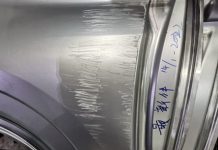
The comparison between the observed wrinkles in the produced part and simulation shows that both models (Coulomb friction and TriboForm) can predict wrinkles as observed in production (Figure 6). However, the wrinkles in the produced part were more severe than numerically observed. It seems that the TriboForm friction predicts slightly more severe wrinkling than Coulomb friction, better corresponding to the wrinkles on both sides of the produced parts.

Fig 6. A comparison between wrinkles observed in production (left) and compared with simulations results using Coulomb friction (centre) and TriboForm friction (right)
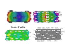
As a final result, a sensitivity analysis is shown in Figure 7, whereby Renault has simulated the part with different levels of lubrication amount, tool roughness and sheet roughness. By setting these different levels in TriboForm, and running AutoForm simulations with the resulting friction models, Renault was able to simulate the forming process including variations that can occur in press-shop reality. The results show the sensitivity of the part to tribological conditions, as the split appeared for more extreme friction conditions.

Fig 7. Sensitivity study demonstrating the sensitivity of the part to tribological conditions.
Once again superior accuracy is demonstrated using the influence of tribology, friction and lubrication in sheet metal forming. Most importantly production issues, namely draw-in, wrinkles, thinning and splits can be simulated accurately by accounting for an improved description of friction conditions using TriboForm and AutoForm. Finally, Renault was able to improve the part by controlling, adjusting and optimizing the tribological conditions as a result.


