
AutoForm’s plan to revolutionize crash simulation accuracy in the automotive sector
Introduction
Crash simulation refers to the use of computer software to evaluate a vehicle’s crashworthiness. It is an important test in the automotive development process that provides valuable information about vehicle strength and passenger safety in the event of a crash.
Many countries, especially those in the automotive triad (United States, Europe, and Japan), impose stringent crashworthiness requirements on new automotive development projects. As a result, simulation technology is a very active niche in automotive R&D. In this article, we’ll discuss current vehicle crash simulation technology and how we can further improve the accuracy of our simulation results using real part data.
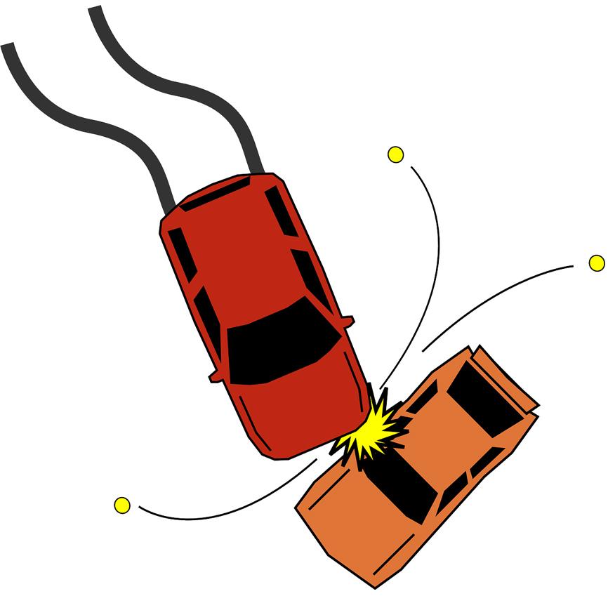
Fig. 1: A crash event simulated during the car engineering phase. The “door impact beam”, part of the door assembly, prevents damage to the passengers.
Evolution of crash simulation
Traditionally, manufacturers depended entirely on physical crashes to collect crash data, then made further improvements through design changes — an expensive and time-consuming process.
Critical tests such as frontal crash, small overlaps, and oblique crashes had to be physically executed to understand collision mechanics against brick walls, cars, or other objects. These tests required multiple models, and after design corrections, the whole sequence had to be repeated all over again.
With the aid of crash simulations to supplement physical destructive testing, crash tests became easier, cheaper, and faster. Over time, they became the predominant source of crash data compared to physical crashes. Today, virtual crash simulations outnumber physical tests by orders of magnitude for all major OEMs. Now, let’s look at current crash simulation practices and what can be done to make improvements.
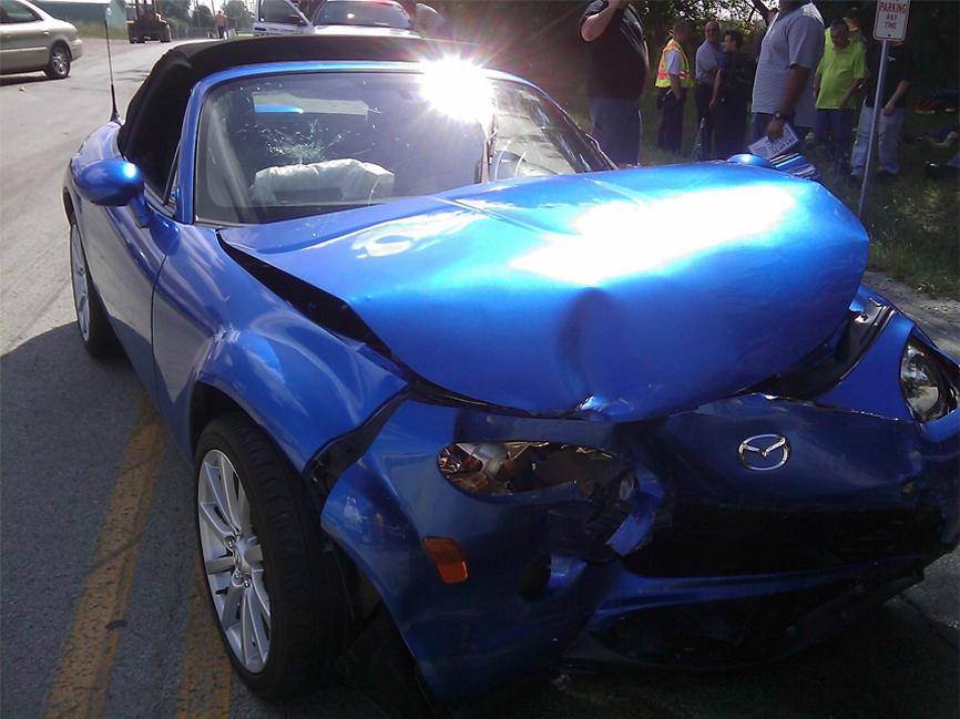
Fig. 2: In the event of a crash, the passenger cabin is ideally not deformed, preventing the passengers from harm.
The as-is workflow analysis
While there are many simulation software options on the market, the two most popular for crash simulation at OEMs require part files to carry out the simulations.
Currently, most companies use part files originating in CAD software such as CATIA or Siemens NX. These files use a certain material type and constant thickness for parts. There is no other information pertaining to the strain value or thinning due to the metal forming operations. The result is not entirely accurate, as this CAD geometry does not give us the complete picture.
We know from experience that any formed part undergoes changes in thickness, hardness, stiffness, and strain throughout a forming process. These changes may be easier to track for a simple process, say flange bending only. However, when more complex or multiple processes such as drawing, hot forming, and hydroforming are involved, the material characteristics can change significantly. At this point, the material information used in the crash simulation may no longer be an accurate representation of the actual part.
Consequently, the crash simulation of formed parts uses part data that could be more accurate. At best, you may come close to the actual results due to cold work hardening compensating for the decrease in thickness. But to what extent, if at all, is anyone’s guess.
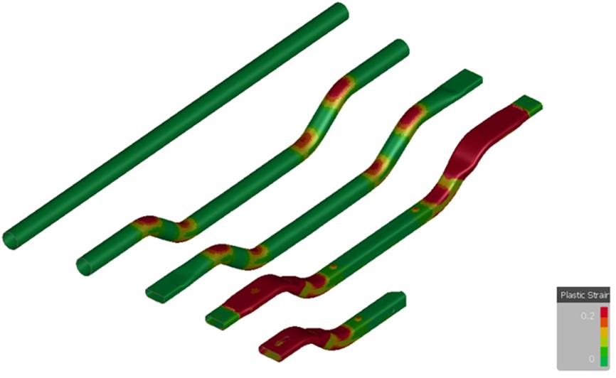
Fig. 3: Uneven strain distribution after a typical hydroforming process. Crash simulation must use actual part information instead of CAD data with even material distribution. The resulting data can be integrated seamlessly with popular crash simulation software.
The to-be workflow
OEMs carry out different types of simulations for their parts. The sheet metal forming simulation, or stamping simulation, is used to predict the success rate of forming operations.
This simulation uses finite element analysis (FEA) to ensure that the produced parts will be defect-free before the manufacturer builds the try-out tooling and starts production. Possible defects in the final part such as excessive thinning, wrinkling, cracks, and springback become apparent after running the simulation.
We propose using the results from AutoForm’s stamping simulation as the source files for the crash simulation. The result is an accurate structure and characteristic representation of the part. The crash simulation results are much closer to reality compared with using the CAD geometry with constant thickness.
Example application of the to-be workflow
Let’s take the example of a car’s A-pillar. When applying the as-is method, we use the theoretical material properties and even thickness distribution for the crash simulation, which is not actually the case in reality.
Using the to-be method, we first run an incremental simulation through AutoForm and obtain the correct hardness information, as the A-pillar is a hot forming part. We also get the actual uneven thickness distribution and the plastic strain information as the forming process stretches the material at different points. Then, by using this actual part information in the crash simulation, the results will of course be more accurate than the as-is workflow.
Is the industry ready for this solution?
Interestingly, we have come across several OEMs and Tier 1 suppliers (serving OEMs) that have realized this shortcoming in the current workflow. There were several support cases in 2020/2021 in which customers enquired about this specific topic.
From a part design point of view, we have received questions regarding the differences in the strength of a part in different regions. For instance, we were asked why certain regions could handle 400 megapascals while other regions could only manage 200 megapascals. We explained that during the manufacturing process, the deformation occurs at different rates throughout the part geometry, leading to varying strength. This is why the material characteristics are uneven at the end of the forming process.
There is a lot of potential for this to-be workflow, especially where there are multiple processes, meaning it is challenging to make a quick estimation of the final material properties.
This is not to say that this workflow is not already in use. Some OEMs and Tier 1 suppliers are indeed already using this to-be workflow for greater accuracy. Nevertheless, many others are still not aware of its benefits. Hence, we at AutoForm are actively working to increase awareness of this workflow in the relevant sectors.
Applying this solution in the current markets
We intend to use CAD part files from market software such as CATIA or NX and set up a process in AutoForm by either using the AutoForm Formcheck simulation or running a full incremental simulation. The results can then be exported in a format compatible with popular crash simulation software, facilitating a seamless data exchange.
This allows the crash simulation engineers to run a simulation with the actual part geometry, comparable to a real crash. By using the correct information in the source file, we ensure a more appropriate crash simulation response. Thus, the workflow can be integrated into the current process with only minor changes.
Using AutoForm provides one more advantage: In some crash simulation processes, the engineer does not have the material properties, so they utilize table of material properties. Thus, instead of the actual properties, the simulation depends on the average of the material property table.
AutoForm rectifies this situation by providing accurate characteristics derived from tracking the material properties at the end of forming processes such as cold forming, hot forming, and hydroforming.
Conclusion
Considering the industry relies heavily on crash simulation software, every new advancement benefits OEMs as well as customers. With the proposed workflow, we can create a far more dependable and accurate crash simulation process. As the use of physical crash testing decreases, we must upgrade our simulation counterparts to be as robust and dependable as possible.


?")


