
In this blog post, Fernando Tersetti, Application Engineer from AutoForm Brazil, offers a comparison of springback results, between the use of a constant force vs. the use of a servo press with an abrupt increase of the force at the end of closing for solving the curling effect of the side wall, demonstrated on an exemplary structural reinforcement part. An example on how to choose the right equipment and material, and deploy the best strategy in this post!
The stamping industry has undergone a number of changes in recent years. The escalation of the amount of materials available, the search for weight reduction of cars, increased efficiency, more daring designs and new processes and so on has made engineering an increasingly crucial department for the success of a project. The use of simulation software supported all these changes mentioned and also brought a reduction in the amount of correction loops in the try-out, while still increasing the quality of the parts and tools.
With the new materials in use today, especially when we talk about high strength materials (HSS) and aluminum, the problem of springback, that previously existed, is amplified due to the typical properties of these materials.
Specifically, if we take a look at the figure below, we can easily understand why an higher yield stress (HSS) and a lower Young’s modulus (Al) generate a higher springback (eel) than what the mild steel generates when applying the same strain (e*) of course.
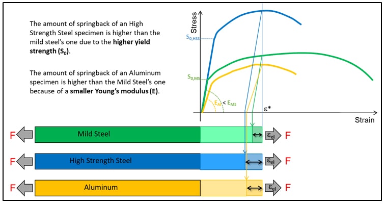
Figure 1 – Qualitative springback comparison between HSS, MS, and Al
Simulation software available on the market allow the measurement and consequently the virtual compensation of this elastic return. They work very well for common materials but may not achieve satisfactory results for high strength steels if the compensation is not made with extreme caution and attention.
An important but often neglected step until today is to find ways to reduce the springback amount with process/product modifications before actually compensating the tools. In addition to these strategies, it is possible to study in depth the behavior of the material to find ways to achieve this goal by controlling the process variables, which in Brazil are often simplified during its development so that they consider the force as being constant during the whole process.
Taking as an example the structural reinforcement shown in the following image, generally made of high strength steel, we can observe some characteristics of its behavior.
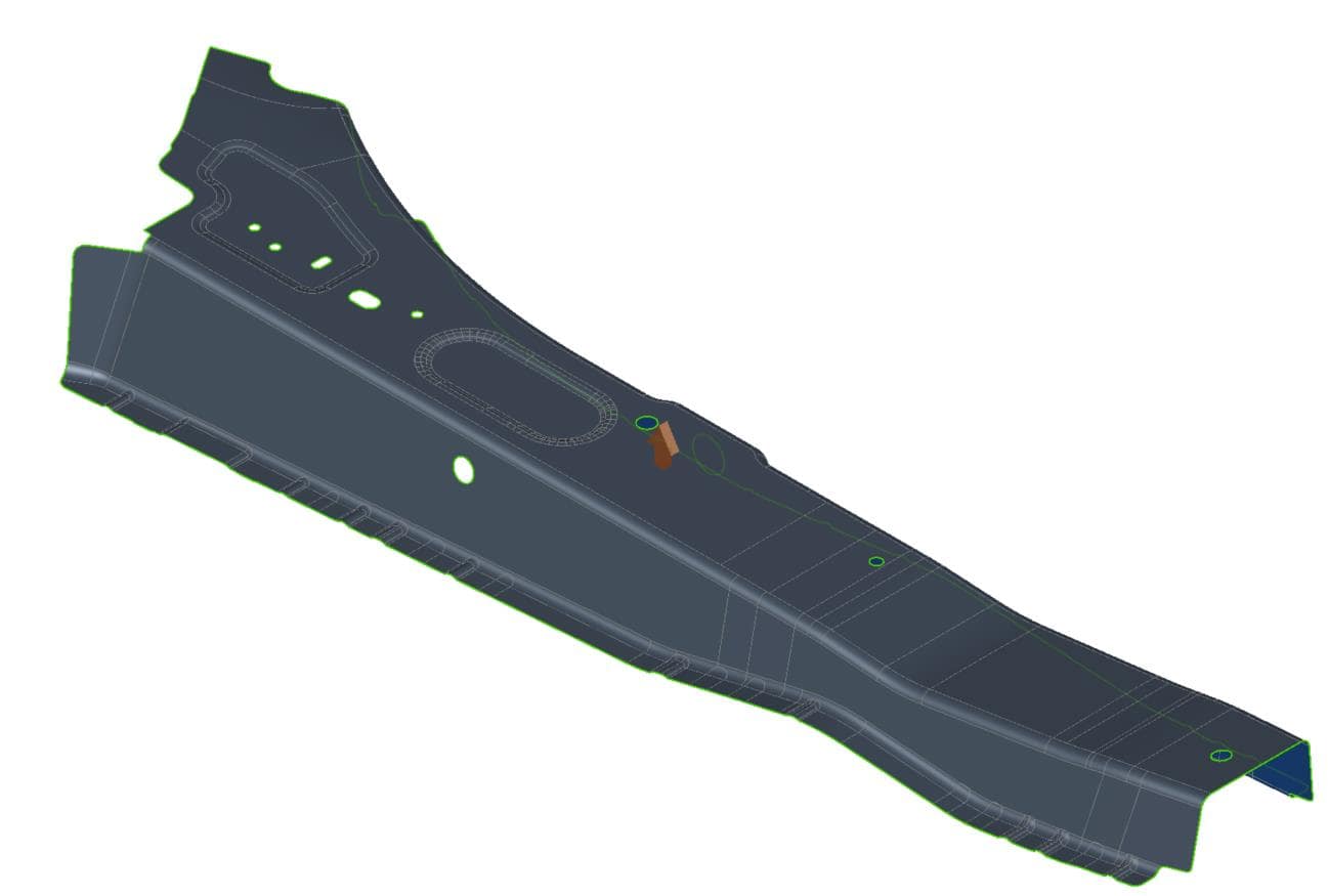
Figure 2 – B-pillar reinforcement
This type of geometry has low stretching due to its uncomplicated shape and the rigidity of the material itself, as well as the characteristic hat-shaped cross section, which limits the conformation options.
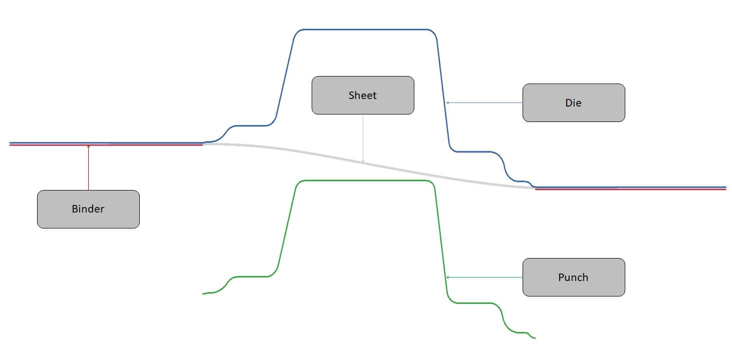
Figure 3 – Binder closure
In the forming process, the sheet is secured between the die and binder, and sequentially the assembly is closed against the punch forming the sheet. The material draw-in is controlled by the force applied to the binder in order to achieve a good plastification level, without splits.
In this specific case the sheet is subjected to a combination of stresses. The first, known as pure bending, occurs in the region indicated in Figure 4, where the initially flat sheet is folded forming the radius of the product. In this condition, the outer layer (fiber) of the sheet is subjected to traction, increasing its initial perimeter. On the other hand, the inner layer is subjected to a compressive stress, reducing the initial perimeter.
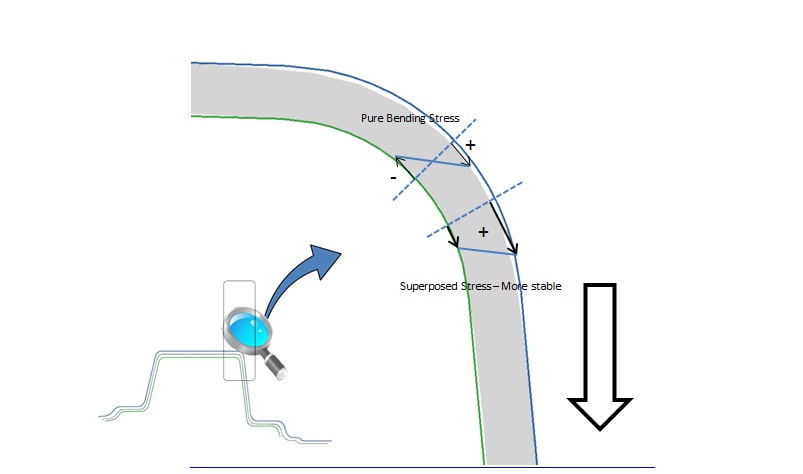
Figure 4 – Stress distribution at pure bending
The second tension which the sheet is subjected to is traction, caused by the force applied on the die by the binder. This traction causes the observed effect on the radius of the product due to the bend (positive stress on the outer shell and negative on the inner shell) to propagate to the full extent of the section wall.
The combination of the above mentioned stresses (called also “superposed” stress) directly affect the springback results and also causes deformation of the wall of the product. An initially flat wall, when subjected to this process tends to bend back, effect known as Curling Wall Effect, where the outer layer tends to shrink and the inner layer tends to extend. This type of defect is very common in parts with this geometry, material and thickness, and can be observed in the simulations results in Figure 5.
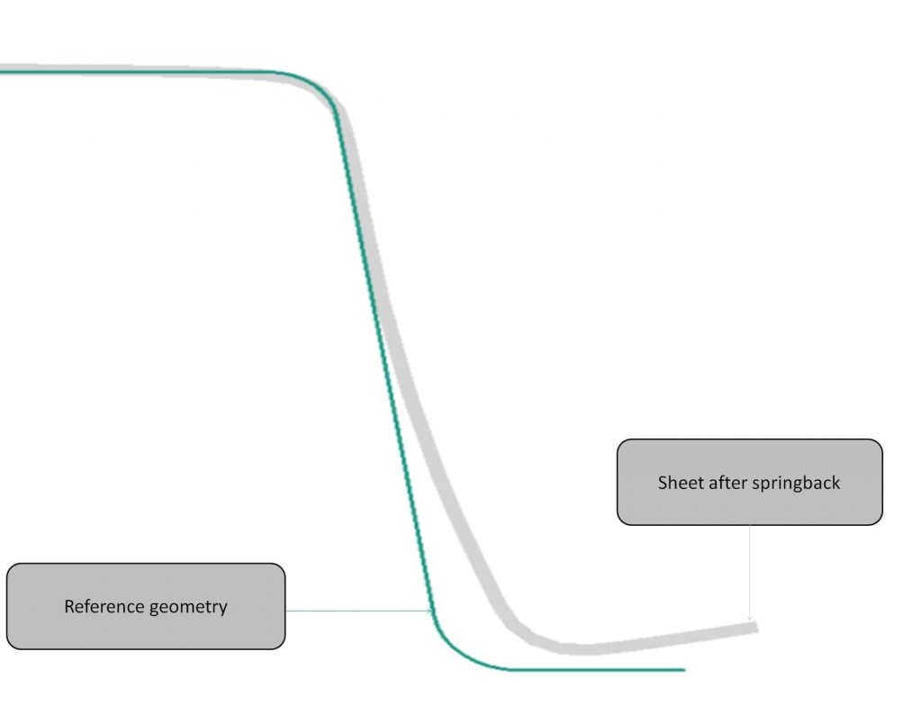
Figure 5 – Curling Wall effect on the product side wall
In the simulation shown in Figure 5 a very common simplification was used in finite element simulations: the force applied to the binder was constant along the press closure, specified for the best condition, without causing splits.
The Curling Wall effect mentioned above can be reduced and even eliminated with the use of variable forces in the binder. This force variation often exists in practice and is, in many cases, disregarded in the simulation. Tools that use nitrogen cylinders do not apply constant force, because the force of this component varies with the cushion stroke. The intensity of this variation can be found in catalogs (figure 6) and inserted into the simulation data.
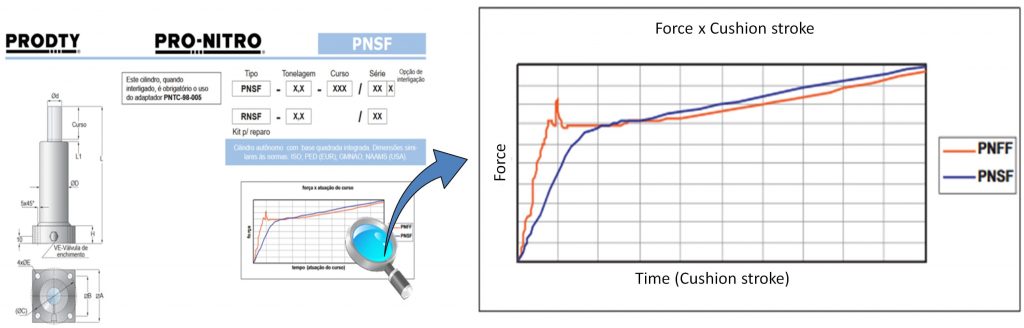
Figure 6 – Prodty catalog
In Figure 7, we can see springback results for the same process using different ways to represent the binder force. The left image shows the initial process, considering a constant force of 80 tons. In the image to the right, the result is shown when the elastic constant of the cylinder is considered in the simulation. The preload (initial force) continues at 80 tons, but at the end of the stroke, the applied force is approximately 115 tons.
The image shows how force variation can affect springback results, and explains why in some cases the theoretical results of the simulation are not achieved in practice.
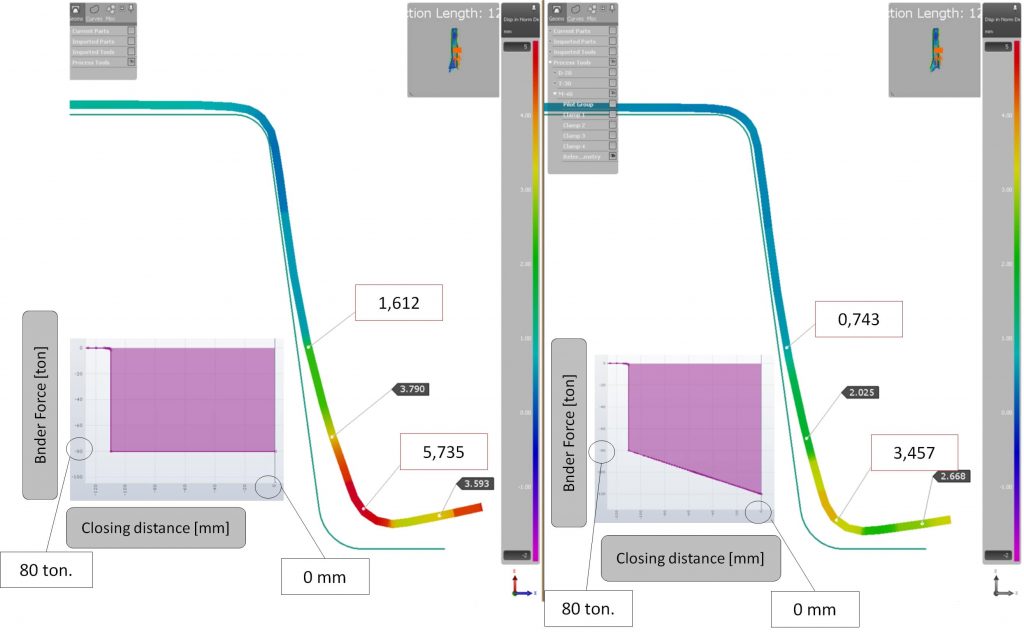
Figure 7 – Constant force vs Variable force (Cylinder)
In theory, this reduction of springback has explanation based on a phenomenon called Post-stretching. The basic idea is, at the end of the process, to apply extra force to the binder which means holding the sheet more. This force is capable of reducing or even eliminating the compression stresses produced on the inner layer of the sheet (only tension stress along the thickness of the sheet) and balance the stresses on both layers, reducing or eliminating the curling effects of the wall.
In the case of tools that use nitrogen cylinders, the effect of post-stretching is limited by two factors: the force variation is not so significant and, in addition, it occurs continuously throughout the press closure.
The theoretical concept of Post-stretching is based on a 5 to 8 times increase in the applied force at a closure distance equal to the die entry radius. For example, if the die radius is 10 mm then the increased force must be applied at 10 mm from bottom. In practice, this can be achieved with the use of servo presses.
Figure 8 shows the comparison between 2 simulations of the same process: the one on the left considers constant force while the one on the right considers the use of a servo press with an abrupt increase of the force at the end of closing.
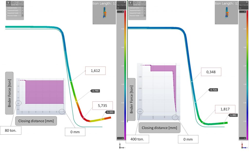
Figure 8 – Constant force vs Variable force (Servo Press)
It is possible to observe a reduction in the value of the springback, before any geometric compensation. An adjustment (springback) of almost 6 mm in the conventional process becomes only 2mm. In addition to the reduction of the springback values a significant reduction in the curvature effect of the wall can be noticed as well.
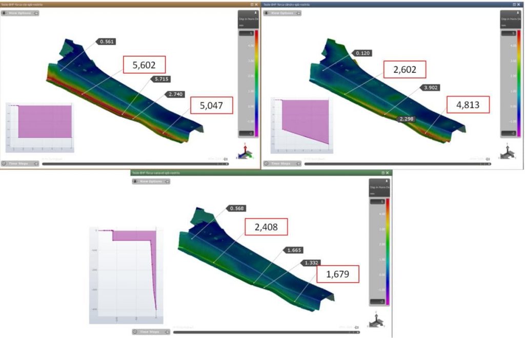
Figure 9 – General comparison (Springback)
As can be seen from the analysis shown, the simulation technologies available on today’s market allow us to predict and make process decisions, choosing equipment and material at an early stage of the process. Basic engineering concepts can be employed to aid development, and often achieve better results than the classical approach.
It’s becoming clear that there is a growth in the awareness for the necessity of investing more time in engineering, simulation and evaluating different scenarios in order to find the most effective results in reality, while reducing the overall cost of development and production.
Note; All examples shown in this paper are derived from theoretical analysis using AutoFormPlus R7 software.
About Fernando Henrique Tersetti
Fernando is an Application Engineer at AutoForm do Brazil and member of the technical team responsible for the support and application of the software in the Brazilian and Argentinian Market. He has ten years’ experience in the automotive industry working in the development of stamping tools and process simulation and has a bachelor degree in Control and Automation Engineering.
Contact: +55 11 4121-1644 / fernando.tersetti@autoform.com.br


