Springback of sheet metal stamped parts is a challenge faced by tooling suppliers and their customers; parts produced in stamping dies require significant effort in engineering and simulation to arrive at reasonable dimensional accuracy during process design. Conventional methods for pursuing springback compensation in stamping dies require a great deal of time to measure springback and to manipulate tooling surfaces in order to counteract the springback deviation from design intent. This challenge is further frustrating as the engineering inputs often vary from tryout and production conditions, making the compensation applied to tooling produce unsatisfactory results.
Godrej Tooling, one of the largest commercial suppliers of stamping tools in India, like so many of their competitors, struggled with springback compensation. They implemented a robust compensation methodology using AutoForm-Compensatorplus and AutoForm-Sigmaplus. Now, using a new springback compensation method enabled by AutoForm software, they can repeatedly create stamping dies that deliver correct part shape in tryout without any re-machining: a major benefit to their Asian, European, and North American OEM customers.
Conventional Springback Compensation

Springback compensation requires repeated modification to CAD die surfaces, which must be validated using FEA
Conventional springback compensation has been performed in the following manner:
- Computer FEA simulation is performed until a “safe” stamping process is found
- The springback displacement from the safe simulation is compared to the tooling shape
- CAD models are modified using a “spring-forward” method
- CAD model is exported for validation in simulation software
- If springback is still outside acceptable limits, step 2 is repeated until acceptable limit is reached
- When the springback falls within an acceptable limit, the tooling surfaces are released for tooling
Like many in the tooling industry, Godrej had initially applied CAD-based compensation under the impression that this saves time. The geometry of the tools used in simulation was always “machine-ready”; once it is found to produce the safe part with good shape retention, process engineers continue directly to solid die design and machining. In doing so, there is significant time spent importing and exporting data between the stamping simulation software and CAD, as well as time spent applying the compensation changes to the tooling surfaces. The system can work, but not without great effort. As more of the tools designed were meant to produce parts with High Strength Steel (HSS) and Advanced HSS content, the number of iteration loops increased, and the exchange of data and constant modification of the CAD surfaces became more costly.
There must be a better way
The intended efficiency of basing every iteration of springback analyses on fully faced machine-ready CAD die face just never paid off. The repeated modelling of compensated CAD surfaces, transfer of tooling objects, and measurement of springback between different software systems and separate engineering departments limited Godrej’s ability to successfully address the springback challenges. Recognizing that the anticipated savings from modeling all tooling surfaces within CAD had not been realized, a decision was made to produce the compensation within AutoForm-Compensatorplus. Additionally, Godrej would modify their engineering workflow to develop a robust and repeatable process using AutoForm-Sigma analyses, to assure that springback corrections would yield the best results under the highly variable stamping environment.
Under the new process:
- Computer FEA simulation is performed until a “safe” stamping process is found
- Sigma analysis is performed to determine that the process is robust
- If the process is repeatable, the tool is a candidate for compensation; if not, the process is modified to define a robust window of operation
- Compensation strategy is defined
- Springback compensation is applied to the die faces within AutoForm
- Stamping simulation is re-run with the compensated die surfaces
- If the springback is within acceptable limits, the compensated geometry is released for surfacing in their CAD system, if not return to step 4 and repeat

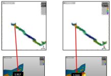
Robust compensation addresses repeatability first then enables direct compensation of analytical models without repeated import-export of die objects
With the help of these new software tools and the improved methods, Godrej was able to improve the quality of part produce in their tools and reduce tryout time. Springback iterations and the application of springback compensation strategy is conducted completely within the AutoForm software environment and within their stamping process engineering department; only after an acceptable compensation geometry is proven to work does the CAD department complete the 3-D modeling of the tooling surfaces. Thanks to the recognition of tooling process robustness and stable process windows along with the easier definition and validation of compensated tool surfaces, Godrej and their customers avoid costly and unnecessary recuts of their dies.
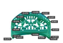
Mr. Vinay J. Gandhi, the senior General Manager and head of engineering, Press Dies at Godrej Tooling, states, “With the help of robust springback compensation using AutoForm-Sigma, we could achieve surface accuracy of greater than 90% for A-pillar in T0 trials without any re-machining in dies.”
AutoForm-Sigmaplus, AutoForm-Compensatorplus, and Robust Compensation


