
AutoForm won the NUMISHEET 2025 Industrial Benchmark by designing a robust forming–trimming process chain that achieves the target geometry after springback—while maintaining high material utilization.
NUMISHEET is one of the most established conference series for numerical simulation in sheet metal forming. Its Industrial Benchmark challenges teams to solve an application-oriented forming task under the same boundary conditions—making approaches and results directly comparable.
The NUMISHEET 2025 Industrial Benchmark challenged participants to design a forming-and-trimming process chain for the Mercedes-Benz T-Node—a stylized geometry representing the lower B-pillar joint. The part is formed from stainless steel 1.4301 at 1.5 mm sheet thickness, with the goal of achieving the target geometry after trimming and springback. The target geometry was provided as an STL mesh.
Benchmark scoring focuses on the following criteria [1]:
- High material utilization is a key factor influencing the product’s environmental footprint (minimizing the blank size relative to part weight)
- The manufacturing of the B-pillar’s lower joint must be repeatable and precise.
- Defect categories to be avoided are tears and wrinkles.
- The focus is on minimal thinning for reliable process control and high material utilization to conserve resources.
Process Chain at a Glance
Material utilization is a key scoring criterion in this benchmark—so we built the process around crash forming. Because the T-Node is used as both a left- and right-hand part in the vehicle, we formed it as a double part to maximize sheet usage. The form blank was defined with AutoForm Trimline Optimization. After crash forming, the two parts were separated.
Springback Compensation—When Geometry Runs into Backdraft
The benchmark target is clear: achieve the STL geometry after trimming and springback. We therefore used AutoForm Compensator to compensate the crash-forming tool based on the deviation between the target geometry and the springback result. In this case, straightforward geometric compensation created a new issue: backdraft in two opposite walls (Figure 1). When two opposite walls become backdraft and remain parallel, there is no tipping direction that releases both sides at the same time. In other words: this backdraft cannot be fixed by tipping—so a purely geometric compensation is not feasible here.
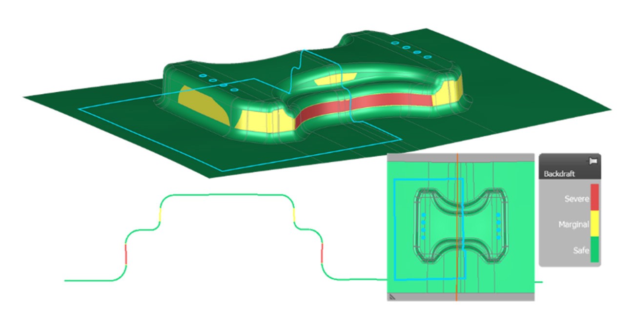
Figure 1: Backdraft in two opposite walls after geometric springback compensation
Fix Backdraft with Normal Stress: Coining Against Springback
To reduce springback—and keep the part releasable despite backdraft risk—we used coining. In practical terms, the radii are pressed with an offset smaller than the sheet thickness (Figure 2). This introduces high normal stresses, which reduce the bending moment through the thickness—and therefore reduce springback. To capture these normal-stress effects in the simulation, we used the TS-11 thick-shell element. Unlike the standard EPS-11 AutoForm shell element, the Thick Shell Element (TS-11) also takes into account stresses in the direction of the sheet thickness.
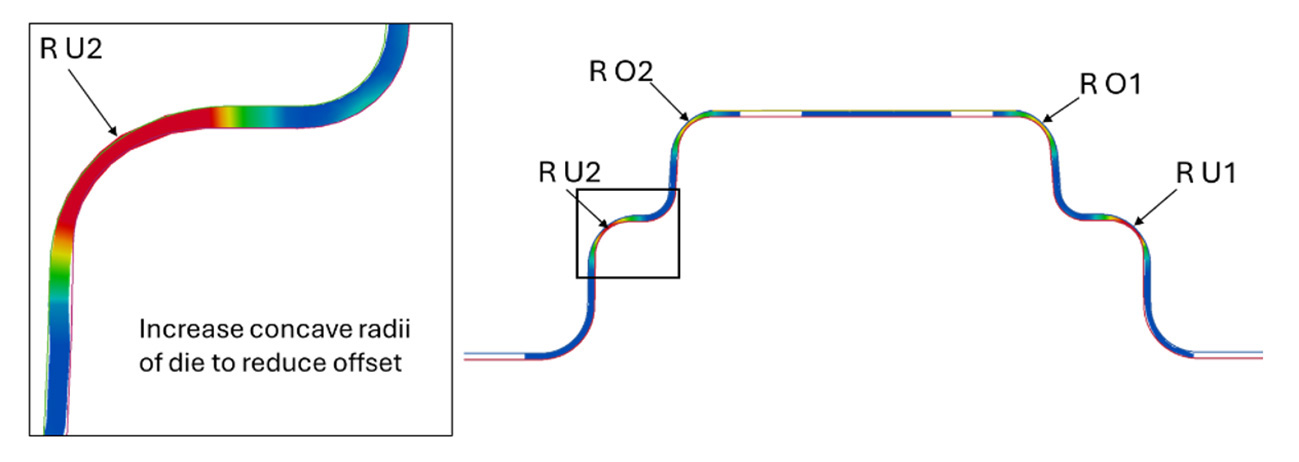
Figure 2: Reducing the springback by coining in radii area
Coining can be very effective—but it can also be sensitive to real-world scatter, especially sheet thickness variation. That’s why we ran an RSPI (Robust Sigma Process Improvement) study in AutoForm Sigma, where key inputs can be systematically varied. By sweeping uncontrollable factors (thickness, yield stress, blank position, etc.), we quantified process robustness and then tuned the controllable levers—here, the Coining Radii—towards a more stable window.
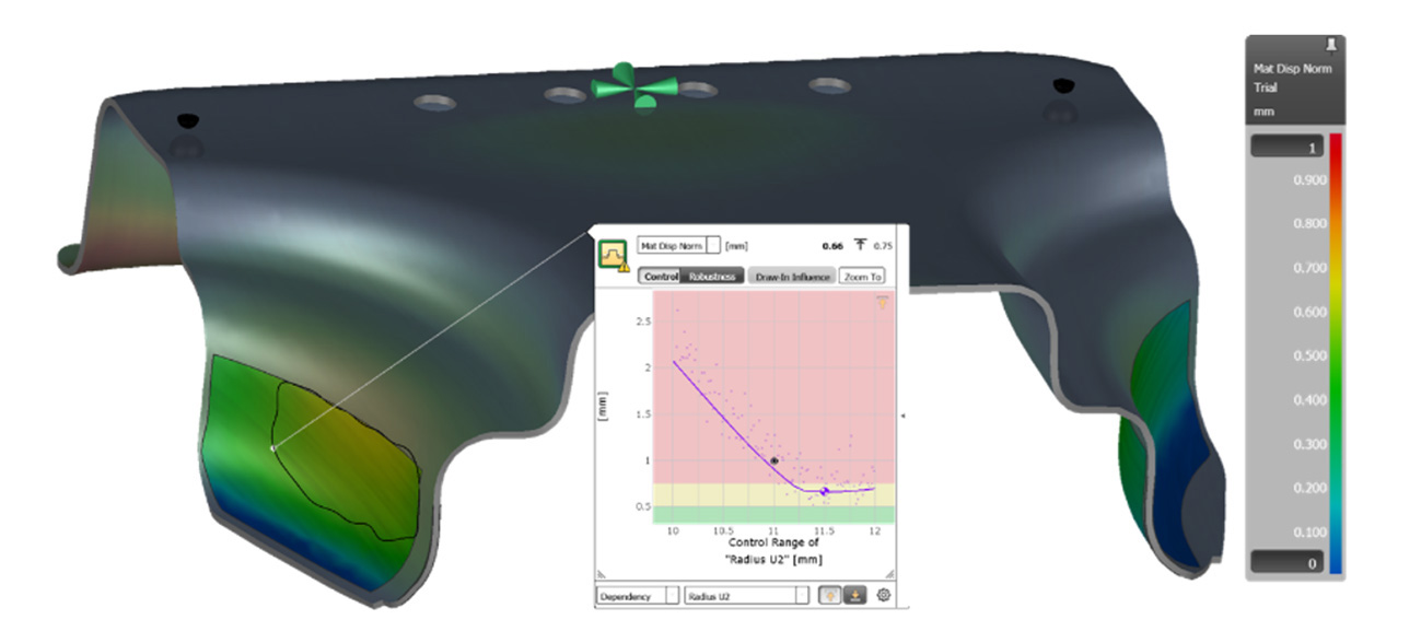
Figure 3: Definition of the evaluation Area for optimizing the Coining Radii
The RSPI study translates directly into a clear takeaway: it defines the process window for the optimized coining radii (Figure 4). Within this window, the process stays robust—and springback remains geometrically compensatable.
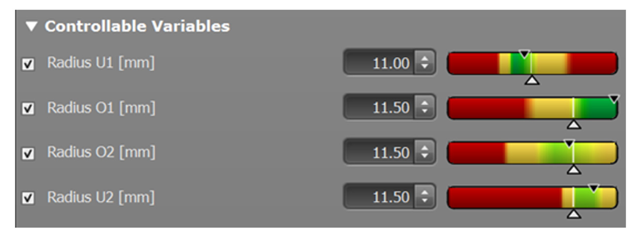
Figure 4: Process window determined for the coining radii with the help of an AutoForm Sigma RSPI study
Next, we incorporated the optimized coining radii into the upper tool using AutoForm ProcessDesigner. With the process set, we ran springback compensation based on the deviation between the target STL mesh and the springback shape. Compensation is inherently iterative: simulate with the updated tools, reassess the remaining deviation, and repeat until the gap to the STL target no longer improves. The iterative springback compensation process is shown in Figure 5.
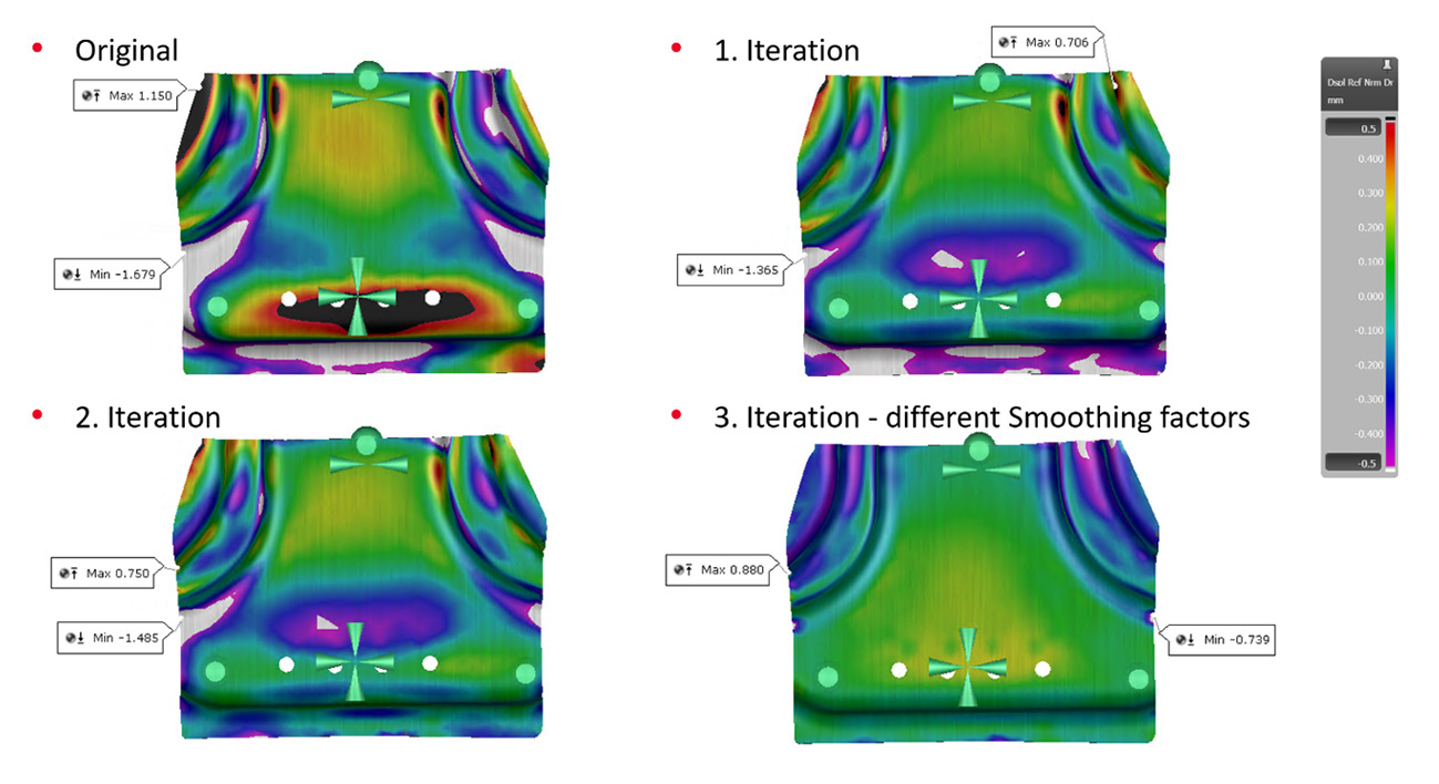
Figure 5: Iterative springback Compensation process
The Next Hurdle: Coining Forces Above 1100 Tons
Coining doesn’t come for free: besides sensitivity to thickness scatter, it also drives very high press forces. In our case, the ram force ramps up to around 1100 tons at the end of crash forming (Figure 6).
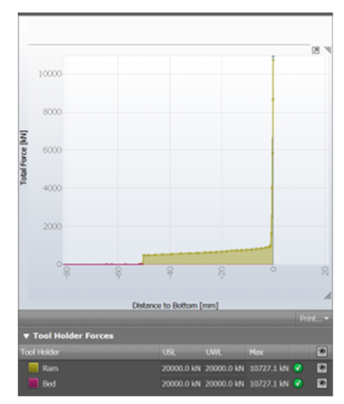
Figure 6: Ram Force over 1100 tons because of the coining process
What does that mean for the tool? We checked it with AutoForm Elastic Tool Deflection (ETD), including press stiffness. The result: a maximum tool deflection of about 0.07 mm (Figure 7). Based on this, we concluded that no overcrowning of the tools was required for this setup.
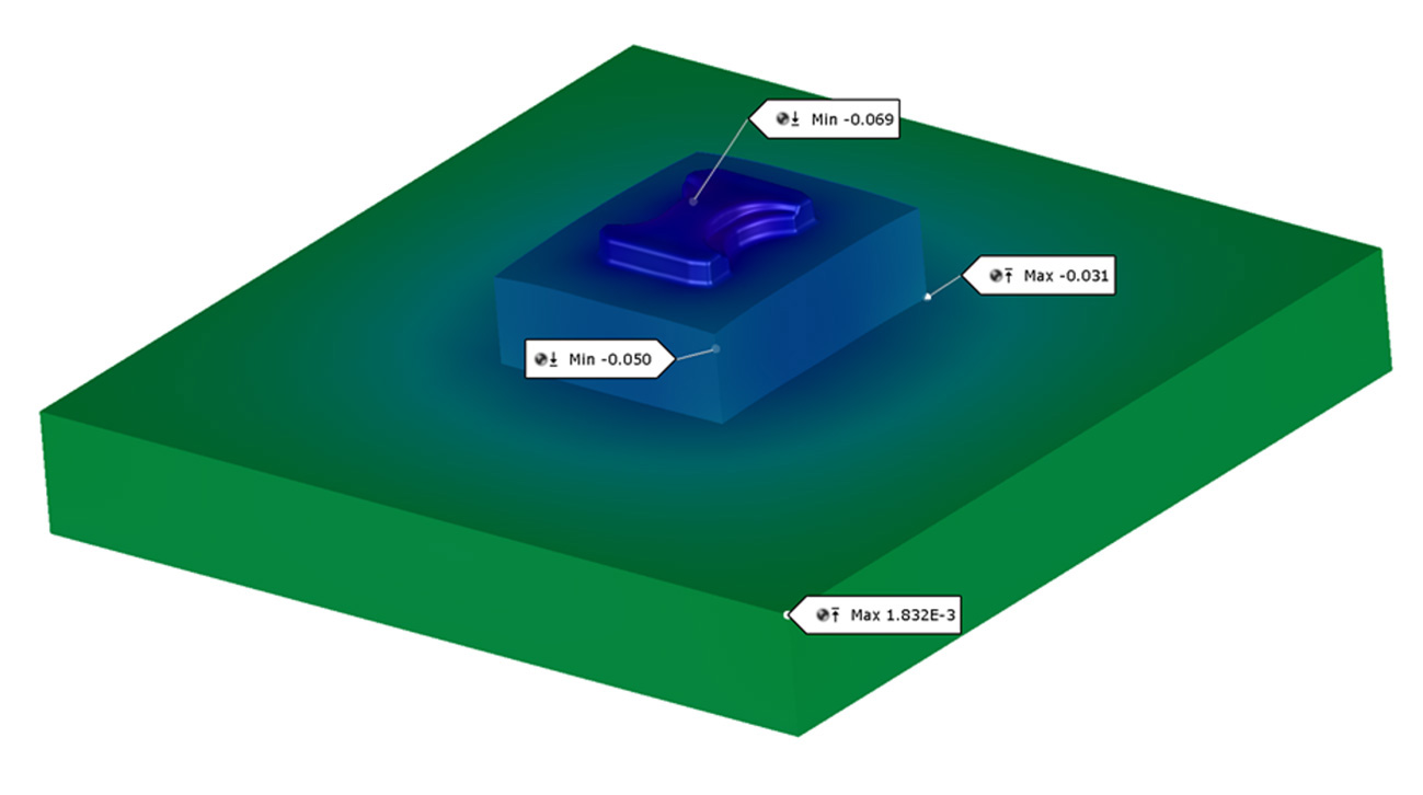
Figure 7: ETD result: max tool deflection about 0.07 mm
How the Field Tackled the Benchmark
The benchmark drew 10 teams from five countries (Germany, China, USA, Italy, and the UK)—from universities to software developers and technical consultants.
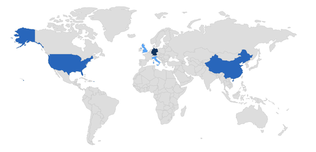
Figure 8: Map showing the origin of the NUMISHEET 2025 Industrial Benchmark participants [1]
Our submission was selected as the benchmark winner, giving us the chance to share the full process chain—from crash forming and coining to compensation and robustness—at NUMISHEET 2025. The key message: combining method know-how with a connected tool chain makes the difference when targets are tight and constraints compete.
Beyond software features, the outcome also depends on applying forming engineering experience to make the right design choices and trade-offs. In practice, it was the combination of simulation capability and hands-on methodology that turned the benchmark constraints into a workable, compensatable process.
See the full whitepaper to review the NUMISHEET results in detail.
References
| [1] | Ott M., Martinitz K., Böhm V., Spörer T., Hartmann Ch., Volk W.: Design of the Forming-Cutting Process Chain for the Mercedes-Benz T-Node (2025) |


?")


