A Case Study on a Side Body Outer Panel Using AutoForm
I
In this article, Li Feng-Xian from SAIC General Motor Co. Ltd Shanghai reveals a case study that identifies the shock line in simulation for a real panel, verifies its accuracy and corrects the issue in reality. Typically, the part is corrected only during tryout, relying entirely on the experience of experts. This case study examined whether or not CAE software can be used to correctly identify and rectify the issue. This is another installment in our series of articles coming from our Chinese customers.
With increasingly fierce competition in the automotive market, requirements for part quality are also increasing. Not only is the quality of the outer surface significant, but also the quality of the secondary exposed surface visible once the doors and hood are opened. Among all defects, the shock line at the threshold of the body side outer is a difficult problem to solve. In order to increase the space of the door opening and to improve the comfort of passengers entering and leaving through the door, part design is relatively compact, and the radii and sidewall angle are small. Consequently, this makes any defects at the shock line more serious.
Presently, shock line issue identification is mainly based on visual inspection methods using light reflection, relying on the subjective judgment of an expert. Moreover, in the process of tryout, the way to reduce any defect is to manually adjust and enlarge the die radii. It is impossible to estimate the validity of the approach in advance. Therefore, it was necessary to find a reliable CAE evaluation method to analyze the severity of the shock line and assist in the design of the drawing surface. This would reduce waste caused by blind die modifications during the trying out stage, and improve efficiency.
In CAE software, there are reliable evaluation methods for splits and wrinkles, which can accurately predict defects and solve them in advance. But the evaluation method for shock lines is not clear yet. The parameters and values used to evaluate the severity of the shock line are unknown. The problem is very complex; cross-examining material type and material modeling, material coating and texture with the actual process in reality. However, this challenging feasibility study was motivation for one step towards verification & validation out of uncertainty. Taking the body side outer as an example, an evaluation method for a shock line using AutoForm software was created and verified.
Creation of the Finite Element Model
The sheet material of the body side outer is hot-dip galvanized cold-rolled steel sheet for automobiles. Its thickness is 0.6 mm, Elastic modulus E is 2.1×10⁵_MPa,Yield strength σs is 156 MPa, Tensile strength σb is 300 MPa, Total elongation is 40%, Hardening index n is 0.21, and Thick anisotropy index r is 1.8.
In order to ensure the reliability of software simulation for , the parameters in AutoForm need to be set accurately, as a set for final validation with the AutoForm Standard of control parameters.
Fig. 1 shows the schematic view of each tool, in which the binder force is 8,004 KN and the drawing stroke of both inner and outer binder is 200 mm.
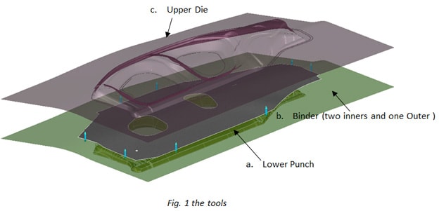
Fig. 1: The tools.
Calculation Results and Evaluation
Below we see the position of the skid line at the threshold of body side outer, physically evaluating the end position of the shock line. A line is set on the die fillet to be the initial position contacted by the sheet metal. When the drawing stroke reaches its end, the final position of the curve flow is the position of the skid line. The method can accurately analyze the position of the skid line according to the principle of the formation of the shock line. Fig. 2 shows that the position of the skid line is 30.2 mm away from the fillet, but the severity of the skid line cannot be evaluated. Further simulation results are needed to evaluate the state of the skid line on the stamped part.
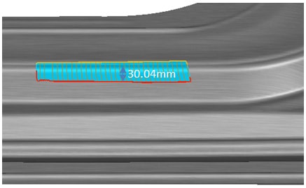
Fig. 2: The position of the skid line at the threshold of the part.
In AutoForm, the result variable unbending strain is defined as the reduction of curvature in the forming process. The calculation method is to subtract the current curvature from the maximum curvature in forming and multiply the material thickness by 0.5. After bending and unbending sheet metal, the state of maximum curvature during forming is recorded. Fig. 3 shows the unbending strain diagram of the part after drawing. The severity of the shock line can be evaluated by using 0.008 as the reference value. If it is lower than this value, the trace of the shock line is not obvious, and it is almost invisible after painting. The shock line in Fig. 3 evaluates the distance from the fillet by the unbending strain to be 29.8 mm.

Fig. 3: The unbending strain diagram of the part after drawing.
In another evaluation proof, the result variable contact pressure shows the normal stress imposed on the sheet by the action of the punch or die. As shown in Fig. 4, the variable max contact pressure can record the maximum contact stress that the sheet has experienced during the forming process. Fig. 5 shows the max contact pressure diagram of the part after drawing. 7% of the sheet yield strength is used as the reference value to evaluate the severity of the shock line. As shown in Figure 5, the shock line of the sheet is 29.4 mm away from the fillet.
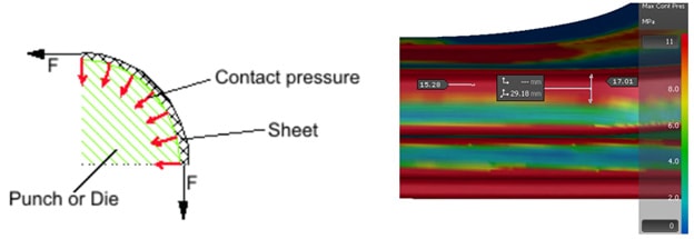
Fig. 4: (left) Contact pressure. Fig. 5: (right) The max contact pressure diagram of the part after drawing.
Comparison of Simulation Results with Actual Production Results
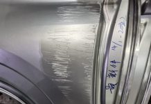
Below we see the actual shock line at the threshold of the body side outer. The position is 29 mm away from the fillet, which is similar to the position in the CAE simulation. The trace is very deep and obvious.
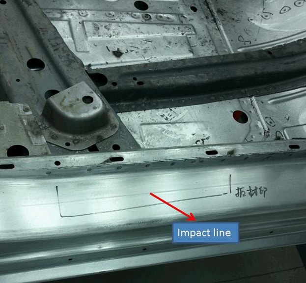
Fig. 6: The Shock line on the actual part.
In order to avoid the shock line defect, as shown in Fig. 7(a), in the CAE simulation, the partial sidewall angle and the die radius of the drawing surface are increased, as well as the corresponding draw beads at the inner and outer side. The simulation results show that the max contact pressure is reduced to about 10, as shown in Fig. 7(b). The simulation shows that the improvement effect is obvious, and the part has no risk of splits, so the modification of the die was carried out by this scheme. Fig. 8 shows the actual part state after modification, and the trace of the shock line has been lightened significantly.

Fig. 7: Die modification and shock line simulation results.
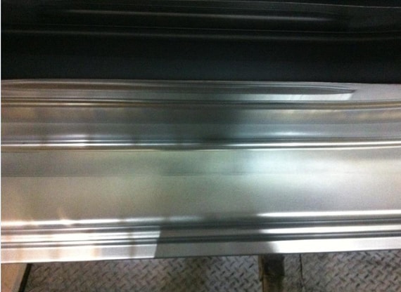
Fig. 8: Final surface quality of the part.
Conclusion
The example of a body side outer shows that the shock line of the stamping parts can be accurately predicted by the AutoForm CAE software. With the CAE software, the shock line can be evaluated in advance and an effective solution can quickly be found, thereby avoiding repeated repair and modification after the die is manufactured, shortening the die manufacturing cycle, and improving the manufacturing quality of the parts.
Li Feng-Xian
Vehicle Manufacturing Engineering, Press Die Process and New Project Section
SAIC General Motor Co., Ltd. Shanghai 201201
Further reading:
[1] Fu San-ling. The Solutions of Impact Line in Covering Panels[J]. Die & Mould Manufacture, 2014, 3:19-23.
[2] Ma Zhi-yan. Numerical Simulation Technology and Applications in Punching Process [J]. New Technology & New Process, 2014, 8:12-14.
[3] Chang Gui-jing, Liang Gui-rong, Zeng Bing-hua. Forming simulation and process optimization for automotive side body outer panel [J]. Die & Mould Industry, 2015, 41(2):73-76.
[4] Tang Guo-xin, Zhou Fang, Lou Xin-Yong. Cause of shock curve at automobile door plate surface and elimination method [J]. Die & Mould Industry, 2012, 38(7):44-46.


