Introducing the Adaptive Equivalent Drawbead Model with Dr. Igor Burchitz, Technical Product Manager
In this article we cover a new adaptive line bead model which was developed during a recent project. Their goal was to increase the speed of the computation times for simulation.
Drawbeads are used in stamping tools to control the material flow. However, the application of typical geometrical beads results in extended modelling efforts and computation times. This is not acceptable anymore – especially considering early process development stages. Here, the option of having a lot more of part/die design rework cycles is beneficial for the part quality – or if not necessary a resulting shorter lead time could be translated into substantial cost savings. To help address these requirements five stamping experts joined forces to develop a solution and they were successful.[1] But what is so special about their model?
Their solution was to provide a computation that continually updates according to the changing conditions which occur during the actual forming process. In the calculations the adaptive line bead’s geometry is treated as if it was a 3D object, incorporating relevant phenomena such as hardening curves, yield surfaces, stress effects on thickness and contact description.The team started with the old model available in AutoForm^plus R6. However while that model resulted in an effective description it also showed limitations. The team then developed several extensions to improve its accuracy.
Adaptive Equivalent Drawbead Model
Igor Burchitz, Technical Product Manager at AutoForm said:
‘Calculation of the lever forces generated by the bending moments at the groove radii were improved to get a more accurate prediction of the drawbead uplifting effects. Additionally, a more accurate approach was introduced to get the actual sheet bending shape within the drawbead zone. It is known from reality that when for example using a rectangular bead, depending on the profile geometry it might happen that the sheet will assume a rounded shape after the forming of the bead. At the same time, the sheet bending shape does not always remain the same during the forming process. – To capture these effects a new algorithm was developed to calculate actual sheet bending shape iteratively based on geometric constraints and momentum equilibrium. These improvements lead to an improved calculation of bending work and therefore higher accuracy in calculation of drawbead restraining and uplifting.’

Figure 1: For the geometry and strain the distribution of the longitudinal strain was defined in five sections of constant curvature, whereas the model employed in AutoForm^plus R6 used just three sections (1, 3 and 5 in our notation).
Application and Results of an Industrial Test
The team did not leave us hanging when it came to validating their results. Using their proposed equivalent drawbead model they tested ran a drawbead test at Mondragon University (Spain) in close collaboration with Matrici S. Coop. AutoForm here fully acknowledges ‘the fruitful discussions and valuable support of both customers during this project.’[2] The part itself had been previously used as the Numisheet 2005 benchmark, making it an ideal candidate.

Figure 2: Underbody cross member. Sections to measure: a) draw-in; b) strains and part shape, [5].
The blank material for the part was the aluminum alloy AL5182-O. In order to test the formula’s efficacy two simulations were run to allow for comparison with real measurements.
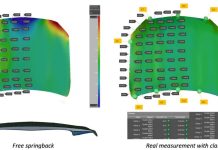
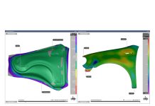
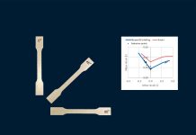
The first simulation was run using geometric beads and the second was run using the proposed adaptive line bead model. The resulting upper die force predicted by the two simulations was similar in result (about 1700kN). Figures 3-4 show a comparison of material draw-ins, the true thickness strain that occurred after forming and part’s actual shape after springback.
Although the results calculated using geometric beads were similar in result, it was also demonstrated that the adaptive line bead model provided a positive prediction for the type of variables used to validate a process. Furthermore processing CPU time was some 2.5 times faster compared to calculations run using the geometric beads simulation. Therefore the proposed line bead model put forwards by the project ‘can be considered as more efficient way to incorporate drawbead effects in simulation.’[3]

Figure 3: Simulation results: a) material draw-in after drawing; b) true thickness strain in section I

Figure 4: Springback profiles at sections I and IV.
Thank you for reading, and don’t forget: subscribe to this blog to get our most important blog post delivered to your inbox. We will not share your information or send you any marketing emails.
Further reading:
- Stoughton T.B.: Model of drawbead forces in sheet metal forming. Proceedings of 15th Biennal Congress of IDDRG, Dearborn, MI, 1988
- Matiasson K., Bernspang L: Drawbead modelling in sheet metal stamping simulation. Proceedings of 4th Numisheet Conference, Besancon, France, 1999
- Yellup J.M., Painter M.J: The prediction of strip shape and restraining force for shallow drawbead systems. Jounal of Applied Metalworking, Vol. 4, No. 1, pp 30-38, 1985
- Sanchez L.R., Weinmann K.J.: An analytical and experimental study of the flow of sheet metal between cirular drawbeads. Jounal of Engineering for Industry, Vol. 118, pp 45-54, 1996
- M. Smith, F. Pourboghrat, J.W. Yoon, and T.B. Stoughton, editors. Proc. of 6th Numisheet Conf., Detroit, MI, 2005
[1] The project comes from three AutoFormers: M. Sester, I. Burchitz and B. Carleer, and E. Senz de Argandona from Mondragon University in Spain and F Estalayo, from Matrici Spain.
[2] Igor Burchitz.
[3] ‘Accurate Drawbead Modelling in Stamping simulations’ Numisheet 2016. Actual source for this article.


