Systematic Process Improvement for Drawbeads vs. Manual Trial and Error
Tool tryout is an iterative process that aims to deliver a die capable of producing parts according to the engineering intent. How long this process may carry on is, to some extent, undetermined since it depends on how close the die is to its engineering intent and its engineering quality (along with other variables).
The iterative process consists of stamping the panel, comparing the real results with what was simulated (engineering intent) and modifying the tool whenever issues and significant differences arise.
In my personal experience, 10 out of 10 times a comparison is made directly with the results (output), while neglecting or not considering all of the input data. Instead, factors like setup, geometry shapes, etc. are taken for granted — and herein lies the problem.
I was recently told by a tryout team member, “Our goal is to match the results, not the input.” This was in response to my question of whether they’d completed a check on the die geometry and specifically on the drawbeads before actually stamping. “The die comes from the milling department and I have a signed paper confirming that, so why should I waste time checking if somebody else did his job right when it costs the department more? Plus, it’s my responsibility to fix it, anyway,” he concluded. Yet, what if there’s a way to nip it in the bud before it requires fixing? Most of the time, it comes down to differences between the geometry of the “real” drawbeads and the engineering intent.
When something like this occurs and you’re already in tool tryout, this train of thought is absolutely true. You have to fix it anyway. But if you know where important discrepancies occur, you may save a lot of time (meaning cost to your department and possible delay in releasing the tool to production) — instead of looking for a new “working” drawbead configuration when engineering has already done it.
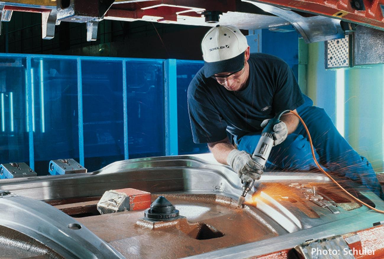
Photo credit: Schuler Group
Every time I’ve faced this situation, the question is always: Why is there such a difference? Who didn’t do their job correctly? Is it the milling department? If not, then who?
A more constructive question: Is it a single person’s failure or is this a process issue?
To that end, let’s talk about how engineering intent and tool construction may fall apart.
Part of the issue is that the milling department intentionally changes the bead size so they have something stronger to begin working with. This practice has been in use for years as you wouldn’t add material to the beads later on for the purpose of strengthening. Instead, you start with a stronger profile at the outset. In this way, you can grind down to the strength you need by reducing the size.
However, engineering has decided that the bead should have a height of 7mm, as an example. The milling department will then take that figure and in fact start with an 8 or 9mm bead. Their reasoning is that if 7mm is the right size, this will eventually prove itself true as they manually grind down towards that thickness.
Our intention is to provide solutions with a one to one correspondence. The simulation should exactly match what is built. The implication is that these “practical” workarounds like starting from a thicker position are no longer needed. Many of our customers have already abandoned these practices, no longer assuming that tryout needs to build upon an imperfect simulation.
However, as we enter Industry 4.0, simulation is always improving and as we become increasingly accurate, the implementation can be shortened. The best case of ignoring the available digital enhancements means that tryout will spend many unnecessary hours milling down to the dimensions that were already simulated.
In contrast, some of our customers have existing drawbead standards, meaning engineering does not determine the dimensions tryout should use as a company rule. Instead, tryout works off of the drawbead standards and engineering must find the best geometry for the draw-in die to match their predetermined beads. For example, if tryout needs to mill a 5mm bead, all other parameters must be consequently adapted to achieve a part that won’t split. As a result, engineering adjusts their calculations according to the milling department, which is also not ideal.
Instead of matching reality to an ideal configuration, constraints have been added to the simulation. In fact, when engineering has completed their work only find the tryout result doesn’t match, the issue is usually found in the use of the drawbeads. We have solutions to address this. However, rather than using our software to easily change the beads to compare results, they are forced to use finnicky trial and error approaches.
Then again, some still follow the process of drawing everything in CAD, which is extremely time consuming because you have to understand how the sheet will fit into the bead along with the clearance space. Based on these factors, you more or less retain the metal length in reality. You also need to ensure the groove and the bead are consistent with each other, which you can simulate, but it takes longer because you’re limited to geometrical beads — this can take a full day to simulate. If any splits or wrinkles form, the engineer then uses their experience to readjust and redraw the settings bead, creating the simulation all over again. By this method, engineers are suck performing single simulations and laborious manual adjustments. And even when they use simulation software, not every solution comes with a drawbead generator — which is the key to our discussion.
It is our firm belief that a process improvement analysis must be undertaken to allow for the bead, as the restraining force, to vary within a certain range — meaning that geometrically, you’re going to change something. From there, you’ll determine the best configuration that avoids splits and wrinkles by performing a robustness and sensitivity analysis on the drawbead sizes themselves.
Usually, the engineering department blames the toolshop and vice versa when these problems arise. However it’s far more efficient to strength their connection using software that spans both departments.
Customers need software that speaks the same language in all three departments: engineering, milling and tryout. When talking about drawbead configuration, we can have dozens of parameters. To avoid discrepancies between departments, we need a software that can create the same drawbead shape using all these parameters in both CAE and CAD. Otherwise, we’ll start seeing differences between the simulation results and the actual build.
Engineers need simulation software that can not only use a force strength factor to reproduce the drawbead, but can also design a drawbead geometry that perform this force factor. Then to be consistent, users in the milling department need to design exactly the same drawbead geometry but in CAD quality surfaces. Finally, the tryout department also needs software that can adjust the first parts to the engineering results. This can only be correctly adjusted if this third software speaks the same drawbead language.
In the end, we all need to work together from every department. Using a software that connects all departments increases communication and provides a more consistent geometry workflow. Naturally, this will save significant time and costs.


