
Introduction
Body-in-White (BiW) refers to the stage in automobile manufacturing where a car’s frame is put together to arrive at the vehicle’s basic structure. Processes such as welding, riveting, brazing, hemming etc. are typical in the assembling operations. Upon completion, the body is ready for the paint process before final assembly.
The assembly process can create challenges, and the components may not go together as well as designed. Even after making tools that create satisfactory individual parts within expected tolerances, the parts may not fit well due to assembly-related factors. In such cases, the engineers can adjust the assembly process, or go back to modify tool geometry and again simulate forming of single parts to try to improve the assembly result. Even with proper knowledge and experience, it can take many trial and error loops to reach a working solution. These intense loops require costly resources and may not quickly provide satisfactory results.
In this article, we shall take a look at how Fontana Group in Italy is using AutoForm’s Assembly Solution to improve this situation by utilizing software to eliminate these trial and error loops and reach the optimum design faster, helping their customers meet the desired time to market.
Current Scenario in Assembly Simulation
While the development in simulating forming of individual parts has been phenomenal in the last two decades, this has not been the case for assembly simulation. On studying the market, AutoForm derived two observations about BiW assembly simulation in the market:
- Available software in the market to simulate BiW assembly is subpar and unable to model industrial processes efficiently
- There is a pressing need for a simulation solution to cut costs and time-to-market for new products.
Speaking to dozens of our customers in the automotive sector, we learned that the current simulation solutions in the market are not able to provide high accuracy when validated with actual assembly results. As a result, few of our customers are currently using any software to simulate assembly for process optimization purposes.
While solutions exist that allow users to do a critical analysis of the BiW assembly, their application primarily focuses on ensuring good weld quality. Factors such as applied forces and kernel size can be evaluated, but they can only be applied to nominal CAD geometry.
In the real world, however, the forming processes used to manufacture components can lead to residual stresses/strains and uneven thicknesses in the part. Additionally there are the effects of gravity and assembly processes themselves that can significantly affect the final assembly quality.
The Team and the Objective
In order to develop and validate an effective solution, AutoForm teamed up with the Fontana Group. Fontana Group has more than 65 years as aluminum tailors, over 1200 employees working in 11 plants in 3 countries. They are a world leader for engineering, die construction, metal parts stamping (including Fontana BLOW technology) and assembly for luxury and sports car sectors. They are a strategic partner for exceptional OEMs, including Ferrari, Rolls Royce, Lamborghini, Maserati, Aston Martin, Alfa Romeo, Jaguar Land Rover, Daimler, Ford, Audi, BMW and Volkswagen (source: https://www.fontana-group.com/en/).
AutoForm focused on creating a robust software solution while Fontana Group delivered their market expertise and stamping and assembly process experience as shown in Figure1. The objective was clear: A coordinated effort to create a dependable software solution. One that was capable of handling all the calculations related to the parts, constraints and the sequence of the assembly process as it occurs in the manufacturing plant.
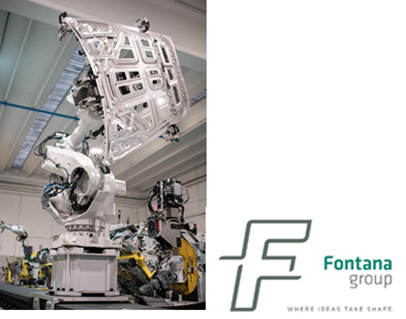
Fig. 1: Typical assembly-hemming operations done at Fontana and today simulated with AutoForm Assembly – (courtesy of Fontana Group).
Focus Areas to Attain the Objective
AutoForm focused on three key pillars in order to create a software that would be able to model industrially relevant processes to a desirable degree of accuracy:
Firstly, the software must include the complete range and scope of the assembly process in use. Different components need accurate positioning and secure holding during BiW welding and other assembly operations, which may be performed by manual or robotic processes. The software must represent fixtures, tools and other process-related factors that have a bearing on the final assembly.
Secondly, the software must be capable of bringing the entire gamut of parts, tools and fixtures together to carry out the assembly process as closely to the real world process as possible. Effective modeling at this stage is paramount for the software to add value to the manufacturing plants and be worthy of purchase consideration.
Lastly, we must add all the technology and processes that are a part of the modern-day manufacturing/assembly process to model a wide variety of operations as reported in Figure2. The software must also be able to identify issues with the springback, tolerance stack-ups, join sequencing, gravity, hemming influence and part positioning for a complete virtual analysis. It must allow the user as much flexibility as possible to modify the process parameters, tools and the assembly sequence to optimize the process.
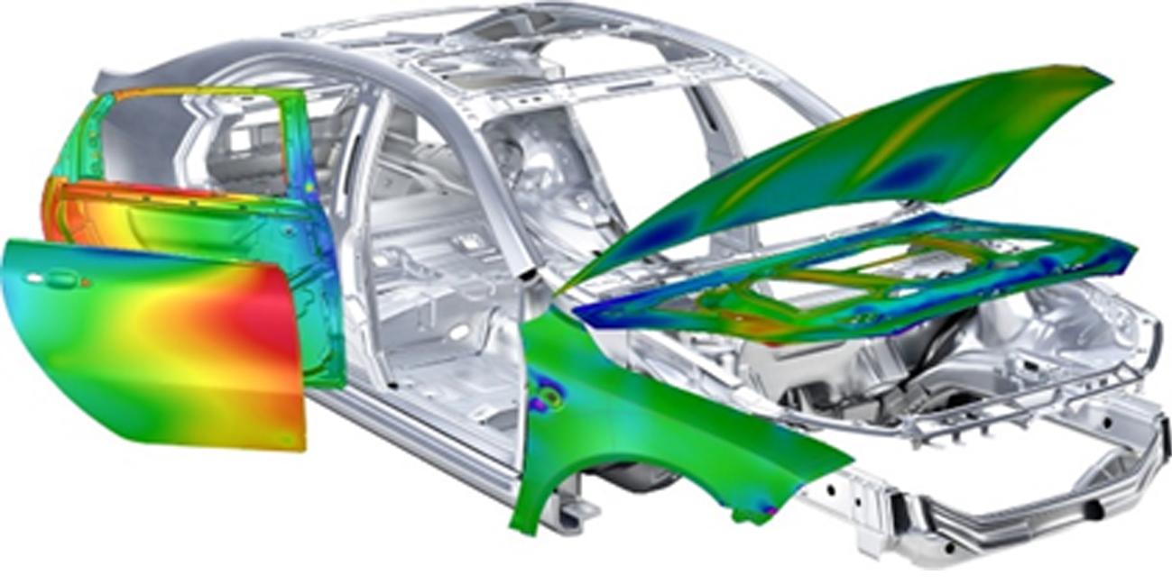
Fig. 2: Simulation of complex assembled component
Roadmap for the Solution Development
After finalizing the objectives, AutoForm laid down a robust plan to achieve them. The development work was divided into two main phases: Process Development and Assembly Validation.
Process Development
In the first phase, we tried to develop the software to a degree where it could model real parts, processes and assemblies. In order to be relevant, it would have to be able to model not only stamped sheets, but also other solid elements that are often joined to the sheets during the process. These solid elements could be tubes, cast parts, extrusions, composite elements, etc., all of which are being used in automobile bodies today.
In order to get there, we started with simpler parts as the actual complexity of the process was not yet a part of the software. Furthermore, we used nominal CAD geometry for the selected parts as stamping simulation data was not available in the beginning. This data was used to design the simulation process, and when more accurate data from the stamping simulation became available, it replaced the initial data. Using this simulation data helped consider factors such as residual stresses, thinning, springback, material variation, geometric revisions, etc., providing greater accuracy of assembly simulation results.
Assembly Validation
The second phase of the development process was about comparing the simulation results to the actual assembly. Because AutoForm does not develop tooling or produce parts, it was important to partner with a company with strong stamping and assembly knowledge with physical parts and assemblies to evaluate. To that end, AutoForm teamed up with Fontana Group in Italy, and the engineers picked a hood assembly currently running production at their factory.
The hood was placed on a measurement fixture to create a detailed accuracy report and to scan the part’s external surface. The key measurement areas were the grille, window, and fender sections of the hood, as the assembly accuracy is critical near mating parts.
The industrial process was complex and consisted of three assembly stations of inner parts followed by a hemming process of the outer and inner parts as sketched in Figure 3. We focused on the mechanical operations and left out the thermal operation of curing. Additionally, for the simulation we used results from the full process stamping simulation as the input, not the nominal CAD geometry.
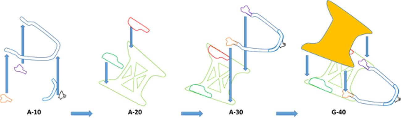
Fig. 3: Schematic representation of the hood assembly process.
The comparison showed that the software results matched the final assembly measurements, and the deviation between the simulation and the actual assembly were found to be within only a few tenths of a millimeter. This meant that the software was capable of simulating the actual assembly characteristics to a high degree of accuracy. The decision to replace the nominal CAD data with the simulation data from the stamping simulation was critical in ensuring the matching results.
Conclusion
The capacity to carry out a wide range of simulations before the production begins has enormous advantages in the automobile development sector. Many engineers understand the need for an assembly simulation solution after having spent countless hours tweaking a part design for favorable assembly results. This is almost always done manually, even in the workshops of leading automobile companies, causing a huge loss of resources.
With AutoForm’s solution, we can effectively simulate and optimize new products as well as those already in production. The amount of built-in flexibility allows the user to carry out a wide range of iterations until the final assembly is within the desired specifications. The end result is a highly efficient car development and production process in a shorter amount of time.
More details of this project are to be disclosed at the upcoming IDDRG conference later this year, so stay tuned to fully see AutoForm’s simulation capabilities in BiW assembly!
Finally, AutoForm would like to extend its sincere appreciation to Fontana Group for their collaboration on this very fruitful project!


?")


