
Why the Correlation Between Simulation and Reality Should Be Your First Check!
In this blog post Matt Kruithoff, Senior Application Engineer at AutoForm, discusses the importance of applying the same forces in simulation as in reality in manufacturing, on the shop floor, and even in production. He delves into engineering settings that will help ensure only the required amount of force is utilized in tryout and how to achieve the best correlation in reality.
One of the most common mistakes I see in tryout is a discrepancy between the forces applied in simulation and what is actually applied in the press. So, whenever I see any variation between the engineered simulation result and tryout, I always check the draw binder forces first. If they are significantly different, the drawn sheet can reflect this by either having splits and/or wrinkles and tryout cannot produce the same positive results achieved in digital engineering.
At the outset, I’ll clarify, I do not mean press forces as such, but refer to forming forces themselves.
In practice, the simulation generally does not take into account all the forces that can potentially play a role in the press for the entirety of the tool. There are many forces generated during the forming operation. When doing a progressive die or line and transfer die, the associated operations generate simultaneous forces in the press, such as trim stations, idle stations, cam stations, etc. The simulation may not have included these stations. You might also have die or cam locating Gibbs or other in-tool components like lifter pads and bars that generate forces, which are not taken into account in the simulation. So, there are several forces that are not typically considered. Although we can simulate a lot of them, most simulation engineers choose not to.
You will often hear that forming simulation forces are too high in engineering. This can work in your favor, because you want to ensure the simulation has enough force to do its job, by having enough force to at least set the beads in a draw and to complete the forming operation. In order to simulate this, our software examines the sheet in terms of forces applied from the upper side and from the lower side, together calculating the total. The upper die cavity, lower binder, and lower post all contribute to forming the sheet metal itself, factoring into the total force.
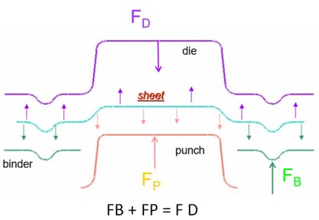
Fig: 1. FD > sheet force on die, FP > sheet force on punch, FB > sheet force on binder
Using Your Forces in Digital Engineering
AutoForm provides settings for rigid stationary tools and moving tools. The upper moving tools and the lower stationary punch are rigid. For the binder, as the moving tool, you can apply either a “gap control,” “spring control,” or “force control.” The binder tool requires enough force to set the bead and then to continue with the complete forming operation.
Here are my binder support type recommendations:
Use a Gap Control setup with the initial simulation and if you need any additional gap and clearance, then start at approximately 5% over the nominal material thickness. For example, if you have 1mm sheet thickness, you should set the gap at about 1.05mm. The simulation software will then maintain that gap. This way you won’t have to worry about the binder backing up and not setting the bead. You’ll have enough force to set the bead and perform the forming operation. It’s important to note that draw binder forces that are too high or too low can impact formability and springback results.
Then you can use the Spring Control setup with the force amount obtained from the initial gap control simulation to begin. Here you can also set the desired pre-load force and spring stiffness values. A lot of simulations are set up using “initial pressure.” However, nitrogen gas springs don’t deliver a constant force because the pressure typically builds as the cylinder closes and gets compressed. By using the spring control tool, you can use the data from the nitrogen calculator. This reveals the cylinder model type, the stroke, and what pressure is generated for the travel of the forming operation. You need a big enough stroke for the cylinder and you may not want to max out the pressure at 2175 psi, in case you wish to add more later on. 1750-1850 psi is therefore a good starting point. Then you can add your springs in to see the forces generated. It gives you the initial (when the binder is set at the top) and final force (compressed) towards the bottom of the stroke.
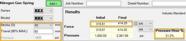
Fig. 2: Nitrogen Gas Spring Calculator
A Force Control binder setup may increase forces higher than required and cause excessive thinning or splits in the sheet if not set up properly. A force-controlled tool will always try to generate enough force to close.
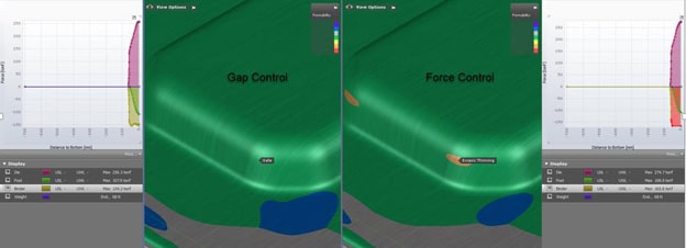
Fig. 3: Comparison Additional Gap & Clearance Control and Force Control with Bottoming in the case of significant thickening under binder
This is largely about having the correct pressure. This goes back to ensuring the draw binder or pad forces are correct when the tryout results don’t match the simulation. Like I said earlier, if I go out to a manufacturing facility during tryout and they say “We don’t have the same results in tryout as we had in simulation,” – then my first “go to” on the check list is “are the draw binder or pad forces correct.”
Form/Trim Pad Support Type Recommendations:
When simulation engineers look at the forces generated for draw binders or pads, you should not take the forces at the bottom of the stroke. Those forces tend to spike excessively. In reality, the tools will most likely be manufactured with the use of stand-offs (spacers) to maintain the desired gap at the bottom of the stroke. And it is generally acceptable if a pad or binder tool were to back off or open within an acceptable range of around .25mm to .50mm from the bottom of the stroke. So when a formed sheet thickens by around 10% in certain areas, then a Gap Control and Spring Control tool is recommended.
Force Control or Spring Control tools are recommended for use with form or trim pads, however the “remove concave radii” function should be selected to lessen the holding tonnage and unwanted deformations to the part sheet. You may also select to remove surfaces that would be cleared or machined away in the actual manufacturing process. This helps to lessen the pad forces and cut out any unnecessary or possible re-forming of the part also.
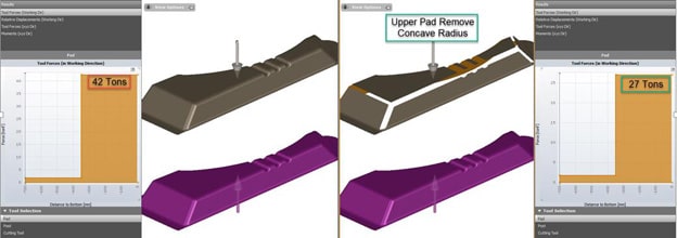
Fig. 4: Comparison between Left: forces without milling, and Right: “remove concave radii” applied.
In the example pictured above, the part has already been formed and we don’t need to reform it again. It simply needs to be held in position for trimming. If you don’t clear those radii out (machine it out) then the simulation will generate 42 tons of force to hold it. If you do clear out those radii, as you would in manufacturing, it will generate 27 tons; quite a considerable difference.
Not Too Little, Not Too Much
Applying the correct amount of force will make all the difference in achieving formability, contributing towards springback results. The overarching goal is to ensure a strong correlation between what is accomplished in simulation and in reality. Engineers need to ensure they apply enough force and tryout should mirror what was done in simulation. This correlation of the forces can quickly be checked if the nitrogen manifold is set too high or too low and you can adjust accordingly. Engineering should also clear out areas that don’t need to be reformed and use only the force required.
May the force be with you! Enjoy your forming!
New readers, don’t forget to sign up to follow our blog. We’ll never send you any marketing emails. Just a once per month feature of our top latest post.


?")


