
Series index. Part 1, Part 2, Part 3, Part 4, Part 5, Part 6
In the development of stamping tools, one difficulty facing toolmakers is adjusting the tool surfaces to consider sheet thickness changes during the forming process. This “spotting” must be performed to ensure the contact between the tools and the sheet conforms to the values defined during the process development. The thickness variations affect the clearance between the sheet and the tool surfaces, and thus have an important impact on the contact pressure between them. So, it is necessary to adjust the tools accordingly to control the material flow during the forming operation and ensure a good quality final part.
Traditionally, the spotting procedure consists of a few specified steps. First, the tools are milled according to the part’s nominal dimensions and the sheet thickness, and the dimensions are checked. Then the tools are assembled and loaded to the press and one initial part is drawn. This produces thickness changes, resulting in stronger pressure contact in areas where the sheet thickens and lower or no pressure in areas where the sheet thins. Different contact conditions can be identified by applying a special paint to the sheet, which wears out where the pressure is stronger. These areas are then adjusted using a variety of large and small hand grinders. Next, another part is drawn, the high contact pressure areas are identified again, and this process is repeated until a homogeneous contact pressure is obtained.
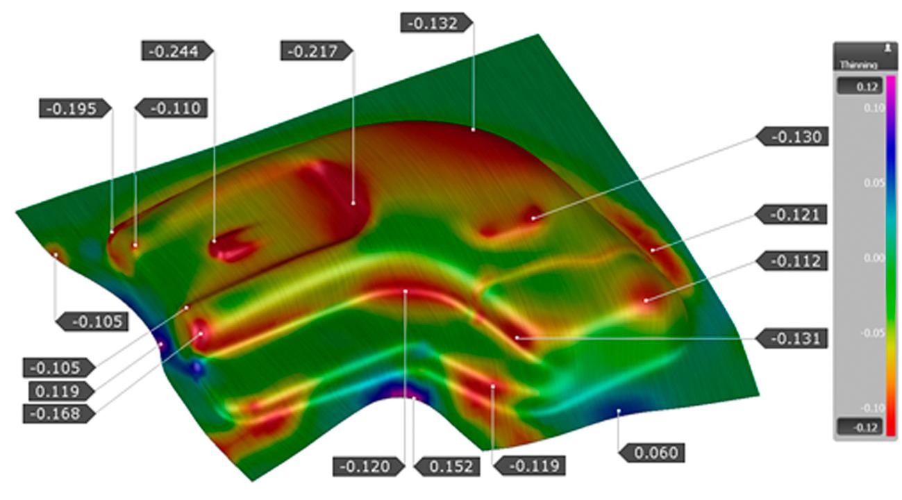
Fig. 1: Thickness changes in the sheet during a drawing operation
Die spotting in hot stamping:
When hot forming, spotting is even more important due to the characteristics of this process. Ensuring the transformation of the material microstructure to the desired martensitic phase requires good contact between the sheet and the tools to allow effective heat flow between them. Perfect contact conditions also help to reduce the quenching time and consequently, the overall cycle time. Any sheet thickness change during the forming process can affect the tool/sheet contact conditions, slowing down the sheet cooling. This in turn can cause warmer areas to develop on the part, preventing the formation of martensite and causing increased thermal distortions in the final part. This is particularly important in the case of patchwork blanks, where high combined thicknesses make it more difficult to cool down the part, especially in vertical walls where it is difficult to obtain a high contact pressure.
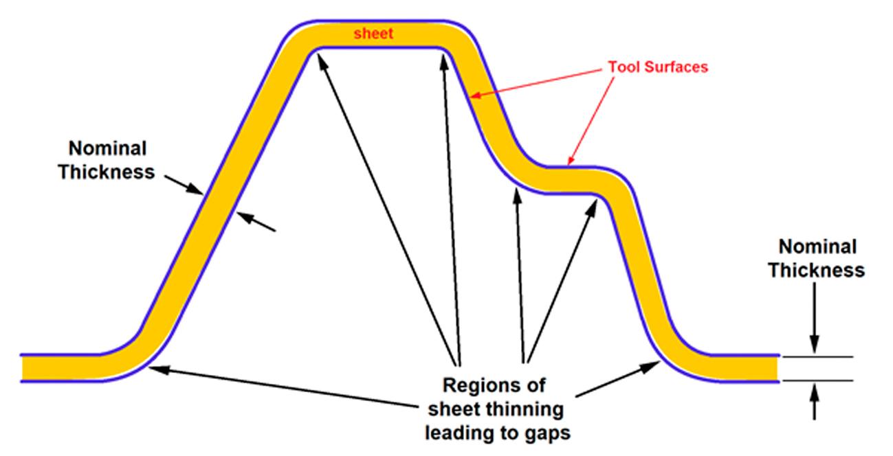
Fig. 2: Thickness changes in the sheet generating gaps during a hot forming operation
The benefits of digital spotting:
As mentioned above, hot forming usually entails a precise adjustment of all tool surfaces to ensure more efficient heat exchange across the entire part surface. Because some points of the part can thicken or thin considerably, the difference between the nominal dimensions of the tools and their final shape after adjustment can be as large as a few tenths of a millimeter, as shown in the image below. So, to ensure good contact between the sheet and the tools across all surfaces, you may need to adjust large areas of the tools where the sheet thickness changed minimally to compensate for thinning at the most critical points. This makes the spotting of hot forming tools more difficult and laborious than cold forming.
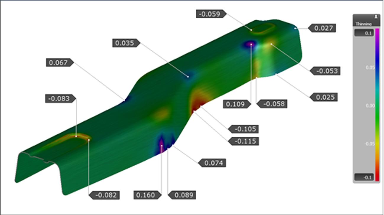
Fig. 3: Thickness changes in the part generating gaps during a hot forming operation
As the grinding is performed manually, obtaining an adequate adjustment is a delicate job that can take a long time and require many parts to be drawn, expending significant amounts of material. As a result, any resource that can reduce the difference between the nominal milled surfaces and the final surfaces of the adjusted tools would be incredibly useful, considerably reducing the time and cost involved in spotting jobs. This is exactly the purpose of digital die spotting.
How does digital die spotting work?
The main principle of digital die spotting is very simple. The final thickness distribution after hot stamping is first calculated by the simulations. Then, digital die spotting allows us to apply this information directly to the tool geometry, modifying the surfaces accordingly. This generates pre-adjusted surfaces that can then be milled to produce tools. It operates similar to springback compensation, where vector fields due to springback are used to adjust tool surfaces. In the case of die spotting, vector fields are generated by using the thickness distribution.
Digital die spotting allows for the application of spotting to both upper and lower tool surfaces, as well as the selection of areas to be adjusted with different spotting factors for thinning and thickening. This means that process engineers can define spotting factors to adjust thinning or thickening values, which should then be reflected on the tool surfaces. It is also possible to neglect thinning or thickening by using a spotting factor of zero for either. An example is illustrated in Figure 4 where different spotting zones are defined with different spotting factors. The resulting spotted tool surface is then shown together with the spotting amounts.
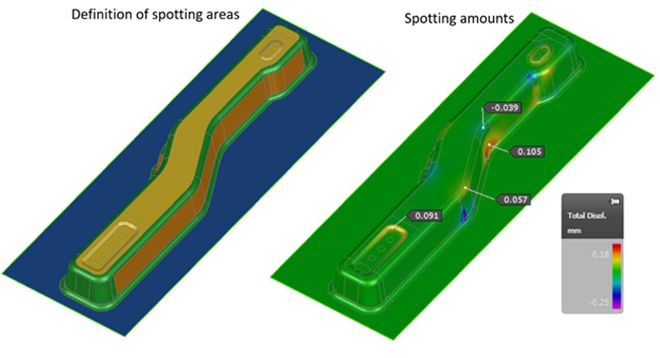
Fig. 4: Regions of the tool with different adaptation parameters for digital spotting
Thanks to these options, the digital adjustment is a very flexible resource that can generate surfaces modified according to the best spotting practices — considering not only the thickness changes but also the side of the tools, above or below, to be adjusted. The final surfaces obtained can be exported as standard 3D files, ready to be milled into tools very close to their desired adjusted dimensions that require only minor additional spotting to achieve the best possible tool contact with the formed sheet. This minimizes the effort needed to finish the tools, with considerable gains in terms of time and costs for the construction and operation of hot forming tools.
Tool spotting is a necessary but very costly and time-consuming process in the sheet metal stamping industry. It is even more critical and challenging in the case of hot forming. To that end, digital die spotting is an important engineering resource that helps to simplify, save time, and reduce costs in the process of adjusting tools before and during their operation. Through digital die spotting, AutoForm further increases its offerings to the sheet metal stamping segment, contributing to the success of its customers in an increasingly advanced and competitive market.
In part five of this Hot Stamping Challenges series, we covered Friction and Realistic Tribology in Hot Stamping. You may wish to start at part one of this series covering New Materials for Hot Stamping.


?")

